-4-
YELLOW wire will be routed toward the fuse
panel.
Caution
should be used when routing
wires. Keep wires away from all hot surfaces,
and any moving parts of the vehicle (radiator
fans, accelerator or brake pedal linkage, etc.).
When routing wires through the firewall, be
sure to pass the wires through an existing
rubber grommet. Failure to do this can result
in damage to wires from sharp metal edges,
and an eventual failure of the security system.
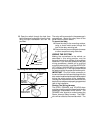
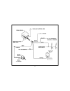
1. RED: (12 Volt Positive Input)
Connect the Red wire of the siren to Positive
post of the battery using the 5/16" ID ring ter-
minal as shown. If your vehicle has side mount
main battery terminals, it will be necessary to
locate an alternate + 12 volt constant source.
If you are unfamiliar with automotive wiring, it
would be best to consult your dealer before
making this connection.
2. BLACK: (Ground Input)
Connect the Black siren wire to a clean
grounded metal part of the vehicle. Drill a 1/
8" hole in your chosen mounting location,
scrape off any paint or grease from the area
and secure the ground wire with the 1/4" ring
terminal and screw provided.
3. WHITE: (12 Volt Parking Light Flash Output)
Gain access to the wires coming from the back
of one of the front parking lamp sockets.
Switch the parking lights on, and locate the
wire that shows + 12 volts on the logic probe.
Switch the parking lights off, and verify that this
wire now shows 0 volts. Connect the WHITE
wire from the alarm to this wire, and insulate
the connection with electrical tape.
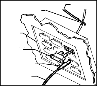
4. Connecting the YELLOW wire
Locate a fuse in the vehicle’s fusebox that
shows + 12 volts on the logic probe when the
ignition key is switched to the “ON” or “RUN”
position, and shows 0 volts when the key is
switched to the “OFF” position (radio or wiper
fuse).
After you have located a suitable fuse, switch
the ignition key to the “ON” position, remove
the fuse, and probe the contacts where the
fuse plugs into. One of the contacts will not
show 12 volts on the logic probe; this is where
the YELLOW wire will be connected.
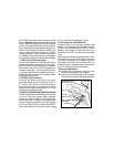
Connection Method A;
A. Locate the wire coming from this fuse
terminal at the back of the fusebox.
B. Splice the YELLOW wire from the harness
to this wire and insulate with electrical tape.
RADIO FUSE,
WIPER FUSES, ETC.
YELLOW WIRE
SPLICE INTO WIRE AND WRAP
WITH ELECTRICAL TAPE
FUSE BOX
FUSE CLIP TERMINAL
(NOT INCLUDED)
YELLOW WIRE
A
B


