


4
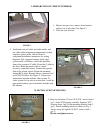
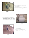
5. Remove and discard (2) two screws from the left
side of VCP. See Figure 4.
6. Insert VCP into mounting bracket (item 3 pg 2) as
shown in Figure 5. Route wiring through opening
in VCP bracket. Connect all wiring to VCP per
instructions included with video system.
7. Check function of all components. See operating
instruction for video system operations check. For
further assistance, refer to the video system manual
for the technical support phone number listed for
your area.
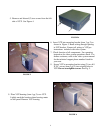
8. Secure VCP to mounting bracket using (2) two # 8
X 3/4" screws (item 2 pg 2) into original holes in
VCP. Do not overtighten screws. See Fig. 5.
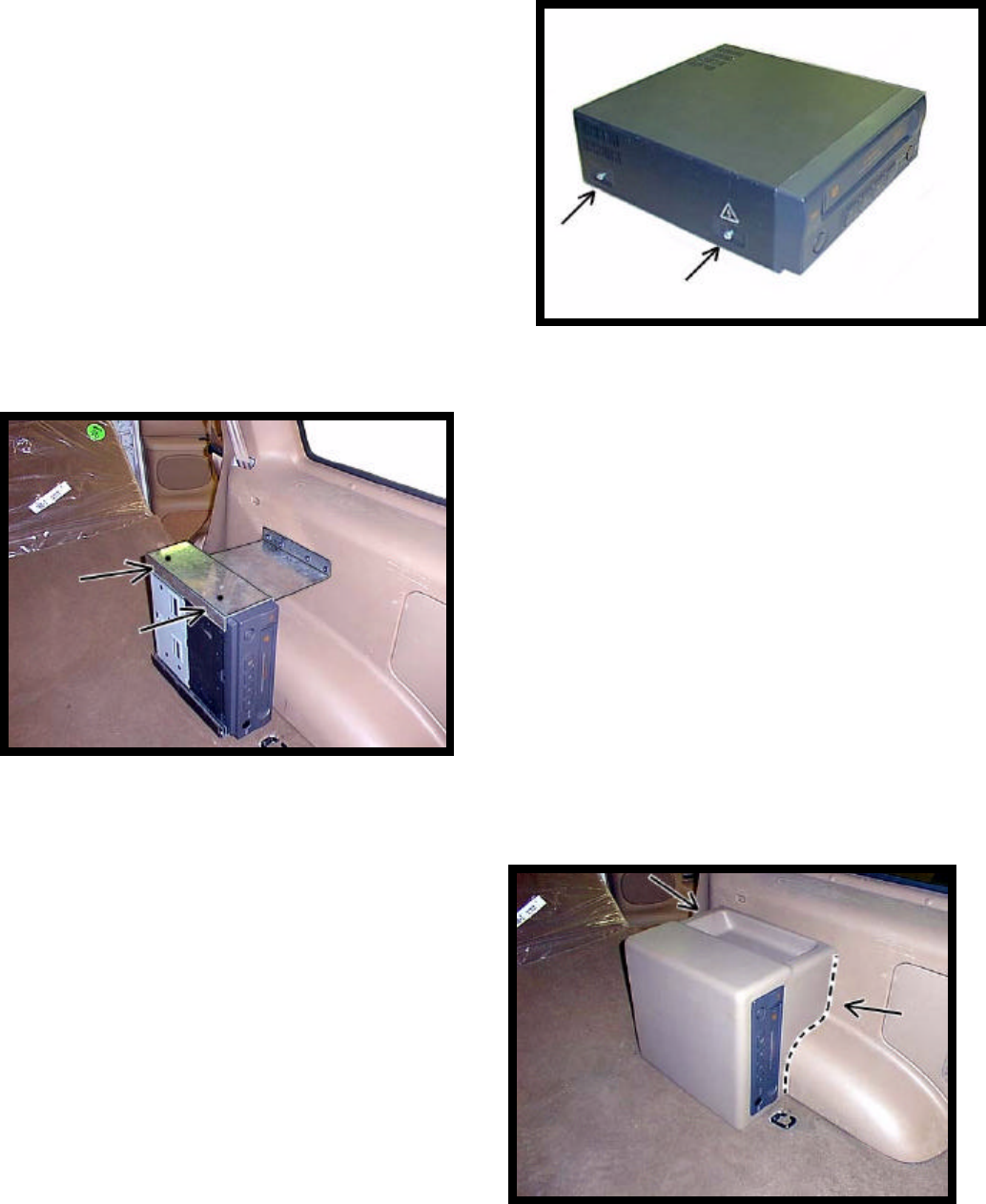
9. Place VCP housing (item 4 pg 2) over VCP.
Lightly mark the location where housing mates
to side panel. Remove VCP housing.
FIGURE 4
FIGURE 5
FIGURE 6