


128-8615
3 of 8
Page 3
Dark Blue Wire: DELAYED 200 mA PULSED OUTPUT / CHANNEL 2
The dark blue wire pulses to ground via an independent RF channel from the keychain transmitter. This is a transistorized, low current
output, and should only be used to drive an external relay coil.
WARNING: Connecting the dark blue wire to the high current switched output of trunk release circuits, and some remote start trigger
inputs, will damage the control module.
In these cases connect the dark blue wire to terminal 86 of the AS-9256 relay (or equivalent 30 A automotive relay), and wire the
remaining relay contacts to perform the selected function of channel 2.
2 Pin White Connector: DASH MOUNTED LED
Route the red and blue wires in the 2 pin white connector from the LED to the control module and plug it into the mating white connector
on the side of the module.
2 Pin Blue Connector: VALET / PROGRAMMING SWITCH
Route the 2 pin blue connector from the override switch previously mounted to the mating two pin connector on the module.
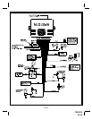
Red / Green / Red w/Black Trace 3 Pin White Connector: Door Lock Outputs
The Red and Green wires will provide a pulsed ground output to the factory door lock control relay. The maximum current draw
through these outputs must not exceed 200 mA. The Red w/Black trace wire will provide a pulsed ground when the unlock button of
the transmitter is pressed a second time after a first unlock command was issued. This is used for second step unlock or all doors
unlock in a two step circuit. In this arrangement Red or Green is used to control the drivers door unlock relay, and the Red/Black will
be used to control unlock of all other doors.
3 Wire Ground Switched Single Step Door Locks
In this application, the red wire provides a ground pulse during arming, or the pulsed ground lock output. Connect the red wire to
the wire that provides a low current ground signal from the factory door lock switch to the factory door lock control relay.
The green wire provides a ground pulse during disarming, or the pulsed ground unlock output. Connect the green wire
to the wire that provides a low current ground signal from the factory door unlock switch to the factory door unlock control relay.
Red/Black Not Used.
3 Wire Ground Switched 2 Step Door Locks
In this application, the red wire provides a ground pulse during arming, or the pulsed ground lock output. Connect the red wire to
the wire that provides a low current ground signal from the factory door lock switch to the factory door lock control relay.
The green wire provides the first ground pulse during disarming, or the drivers door pulsed ground unlock output. Connect this
wire to the drivers door unlock relay that requires a low current ground signal to unlock only the drivers door. If the vehicle does
not have a separate drivers door relay, one will have to be added. Locate the drivers door unlock motor wire and cut it at a convenient
location to allow wiring of an optional relay. Connect the door side of the cut wire to terminal 30 of the optional relay added. Connect
the vehicle side of the cut wire to terminal 87a of the optional relay added. Connect the green wire of the 3 pin harness to terminal 86
of the optional relay added. Connect terminal 85 of the optional relay added to a fused constant + 12 volt source. Most vehicles door
lock/unlock motor legs rest at ground, and switch +12 volts to the door lock/unlock motor legs for operation, if this is the case in the
vehicle you are working on, connect the remaining terminal, 87, to a fused + 12 volt source. In the rare instance that the vehicle door
lock/unlock motor legs rest at + 12 volts and switches ground to the door lock/unlock motors, connect he remaining terminal, 87, to
chassis ground.
The Red/Black wire provides a pulse ground output when the unlock button of the transmitter is pressed a second time after
disarming. Connect the Red/Black wire to the wire that provides a low current ground signal from the factory door unlock switch to
the factory door lock control relay.
Resistive Circuits, As Well As 4 Wire Polarity Reversal and 5 Wire Alternating 12 Volt
Door Lock Control Circuits
These applications require the use of additional components which may include relays, fixed resistors, or for convenience, the AS
9159a Door Lock Interface. Refer to the AUDIOVOX Door Lock Wiring Supplement and or the Audiovox fax back service for information
on your particular vehicle for properly connecting to these types of circuits.