


128-8615
2 of 8
Page 2
Once a location has been selected, check behind the panel for wire routing access, and to confirm the drill will not damage any
existing components as it passes through the panel.
Drill a ¼ “ diameter hole, and pass the red and blue wires from the LED through the hole, from the front of the panel. Firmly press the
body of the LED into the hole until fully seated.
Valet/Programming Switch:
Select a covert location for this switch within reach of the driver of the vehicle. This switch can be mounted below a dash panel,
under the driver's seat. This switch must be within reach of the operator of the vehicle. The locations mentioned are hidden from
view and will be known only to the vehicle operator yet they allow activation of the switch when necessary.
WIRING THE SYSTEM
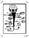
5 Pin Main Connector:
Red Fused Wire: 15 Amp Fused Parking Light Input.
This wire supplies the source for the On-Board Parking Light Relay. If the vehicle’s circuit switches + 12 Volts to the parking light
circuit, connect this wire to a 12 volt source capable of 15 Amps.
If the vehicle’s parking light circuit switches ground to the parking light circuit, then connect this wire to a Ground Source.
White Wire: Parking Light Output (10 Amp Max)
This wire is provided to flash the vehicle’s parking lights. Connect the white wire to the positive side of one of the vehicle’s parking
lights.
Black Wire: Chassis Ground
Connect this wire to a solid, metal part of the vehicle’s chassis. Do not confuse this wire with the thin black antenna wire that exits
the control module independently.
White w/ Black Trace Wire: Positive Output to Siren
Route this wire through a rubber grommet in the firewall, and to the siren location.
Connect the white / black wire to the positive wire of the siren. Secure the black ground wire of the siren to chassis ground.
Red/White Wire: + 12 VDC Circuit Supply.
This 5 Amp fused wire supplies + 12 volts to the module circuit. Connect this wire to a constant 12 volt source capable of at least 10
Amps.
6 Pin Input/Output Harness
Purple Wire: + DOOR TRIGGER
If the vehicle’s door courtesy light switches have a + 12 volt output when the door is opened (most Fords and some Imports), you
must connect this wire to the positive output from one of the door switches. In most cases, the purple wire will only needs to be
connected to one door switch, no matter how many doors the vehicle has.
WARNING: Do not use the purple wire if the vehicle has ground output type door switches. (See Brown Wire.)
NOTE: For vehicles with interior delay lighting see programming under title "Completing The Installation".
Dark Green Wire: ( - ) Instant Trigger Zone
This is an instant on ground trigger wire. It must be connected to the previously installed hood and trunk pin switches.
Brown Wire: - DOOR TRIGGER
If the vehicle’s courtesy light switches have a ( - ) ground output when the door is opened (GM and most Imports), you must connect
this wire to the negative output from one of the door switches.
WARNING: Do not use the brown wire if the vehicle has + 12 volt output type door switches. (See PurpleWire.)
Note: For vehicles with interior delay lighting see programming under title "Completing The Installation".
Yellow Wire: + 12 VDC IGNITION SOURCE
Connect this wire to a source that is live when the key is in the on and crank positions. Be sure that this source is off when the key
is in the off position.
Orange Wire: 300 mA GROUND OUTPUT WHEN ARMED - N. C. STARTER DISABLE
This wire is provided to control the starter cut relay. Connect the orange wire to terminal 86 of the relay. Connect relay terminal 85 to
an ignition wire in the vehicle that is live when the key is in the on and crank positions, and off when the key is in the off position.
(This is where the yellow wire from the alarm should be connected ).
Cut the low current starter solenoid wire in the vehicle, and connect one side of the cut wire to relay terminal 87A. Connect the other
side of the cut wire to relay terminal 30.
NOTE: This is a normally closed starter cut arrangement, and when power is removed from the security system, the
starter disable feature will not operate, allowing the vehicle to start. Audiovox does not recommend using
the Orange wire to interrupt anything but the starting circuit of the vehicle.