


128-8115
16 of 19
Page 16
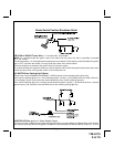
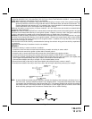
METHOD 2
To connect to the key in sensor circuit as shown for method 2:
A. Locate the control wire that connects the drivers door pin switch to the key in sensor switch.
B. Cut this wire and connect the ignition cylinder side to chassis ground.
C. Locate the key in sensor switch wire that connects the chime module to the ignition cylinder .
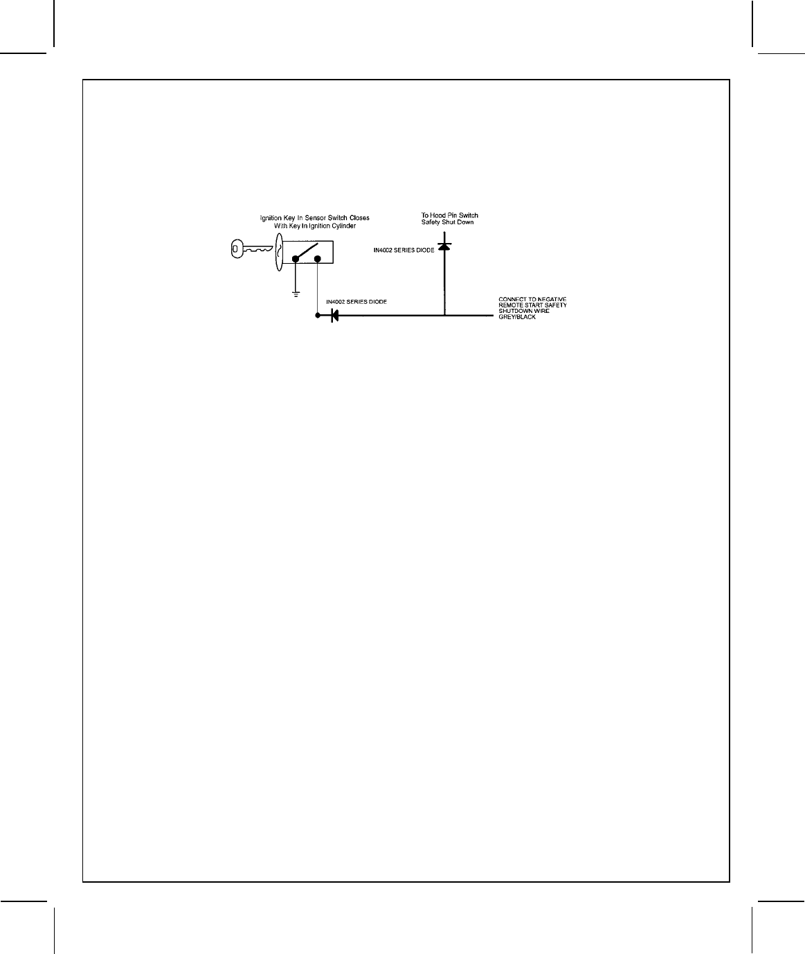
D. Cut this wire and connect the ignition cylinder side to the Remote Start Negative Safety Shut down Wire Gray/
Black, using a 4002 series diode as shown above.
NOTE: A second 4002 series diode may be required to maintain the integrity of the hood open, shut down circuit.
If this is the case, it must be installed as shown in the diagram above. The anode (Non Striped) side must
be connected to the Gray/Black wire of the Remote Start Unit. The cathode (Striped) side must be con-
nected to the hood pin switch. If the hood pin switch is also used for an alarm trigger input, be certain to
use the dual diode assembly packaged with the Audiovox Remote Start Unit as shown in this installation
guide.
AFTER THE CONNECTION OF THE NEUTRAL START SAFETY WIRE AS INDICATED IN ANY OF THE PREVIOUS
ALTERNATE CONFIGURATIONS, THIS CIRCUIT MUST BE TESTED FOR OPERATION.
Retest by following the steps outlined in the NEUTRAL START SAFETY TEST shown in this manual.
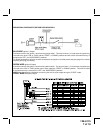
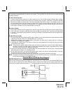
4 Pin Upgrade Telematic Module:
Red = + 5 Volts
Black = Ground
White = Data TX
Yellow = Data RX
If used, connect the 4 pin harness from the Telematic one way module kit to the mating port on the
controlling circuit. NOTE: If using the TWO WAY Telematic module, only Ground, TX, and RX are used on
this port, the + 12 volt supply for the two way module must be sourced separately or the unit will not
operate.
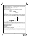
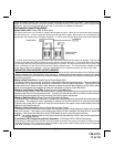
4 Pin Upgrade Data Bus/Flash Logic Module:
If you are using an Audiovox Flash Logic module, it can be connected directly to the Alarm/Remote Start's
control module. Using the Blue 4 pin blue, red, black, & white harness and connect to the mating connector
on the Alarm/Remote Start control module. Wire the Flash Logic/Data Bus module to the vehicle as
prescribed in it's installation guide.