


128-8115
12 of 19
Page 12
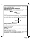
2 Pin Transponder Control Output: (Yellow Connector)
This output is intended to allow the control of a transponder bypass interface module or transponder
bypass relay. The system also allows software selections to control the way in which this output oper-
ates, see remote start feature # 10 for setting this output.
When the unit is selected for output during the start sequence, this output will be active at the same time
Ign. 3 becomes active, and will remain active until the vehicle has started. This will be used for one time
read transponder circuits.
When the unit is selected for transponder on, this output will become active at the same time ign. 3
becomes active, and will remain active all the time the unit is operational under the control of the remote
start. When the unit is selected for continuous and the vehicle is started via the Remote Start, this output
will become active at the same time ign. 3 becomes active and will remain active until the ignition in the
vehicle goes low. This will allow the unit to be used for continuous read transponders circuits.
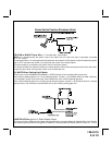
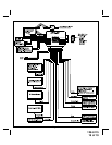
3 Pin Antenna/Receiver Connector: (White Connector)
Plug the previously routed three pin connector from the antenna receiver assemble into the mating connector
of the control module. This connector supplies 12 volts, ground and RF data from the antenna receiver to the
remote start module. Be certain this connector is firmly seated making good contact to the control unit.
NOTE: If the Glow Plug sense wire, Green/Yellow is connected, this wire will have priority over the setting of feature
Bank 3 Feature #11.
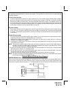
2. Programming Tach Rate:
NOTE: All applications require that tach be programmed.
The unit will not operate unless tach is programmed. If an attempt is made to start the vehicle via the remote start
without first programming tach, the unit will flash the parking lights 7 times indicating tach has not been learned and
stored. If the tach rate is not properly programmed to the specific vehicle, the unit may not realize that the vehicle is
running in certain instances and could re-engage the starter motor.
The Remote Car Starter will learn the tach rate of most vehicles single ignition coils, multiple coil packs, and or single
injector. To learn tach;
1. Turn the ignition key to the ON position.
3. Press and release the program push-button switch 3 times.
4. Immediately turn the ignition key OFF.
5. Hold the program push-button switch ON, then start the vehicle using the ignition key.
6. When the unit senses the tach signal, the parking lights will begin to flash.
7. Release the program push-button switch. The parking lights will turn on for 3 seconds to indicate that the tach
signal is stored and the unit is now out of the program mode.
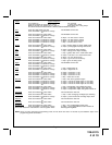
3. Diagnostics:
1. Be sure that programmable feature number #9 is set to the "Diagnostics On" mode.
2. Press and hold the program push-button switch on, then turn the ignition key to the "ON" position.
3. The lights will flash and the number of flashes will indicate the reason for shutdown on the last remote start attempt.
The indications are as follows.
1 Flash 5, 10, 15, or 20, minute run timer expired.
2 Flashes Low or No tach signal received.
3 Flashes Positive input shut down.
4 Flashes Control switch was moved to "Off" position.
5 Flashes RF Shutdown command received.
6 Flashes High RPM signal over speed shut down.
7 Flashes Tach has NOT learned.
8 Flashes Negative input shut down
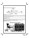
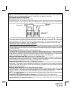
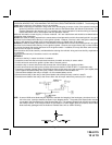
Multi Coil Pack Adapter: (Optional)
The multi coil pack adapter, (P/N 136B1400), is designed for use with vehicles that do not respond to single coil
tach programming. Although the tach resolution of this circuit is designed to interface direct with most vehicles,
there may be an occasion where the following circuit may be required.
To use the adapter, the Green/Black wires must connect to the negative side of the ignition coil(s).
1. For vehicles utilizing independent coils per cylinder, connect the three Green/Black leads to alternate coils. To
achieve optimum performance the coil signals must be evenly distributed. This is accomplished by first
mapping out the firing order of the engine in groups of as indicated below. Draw a circle around any of the