


Installation Guide
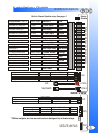
WIRING CONNECTORS
Pink Channel 4 Output Programmable - See menu 2, setting 5.
Green (-) Door Input Negative door pin switch input.
Blue (-) Hood Input Negative input from hood pin switch.
Purple (+) Door Input Positive door pin switch input.
Brown (+) Siren Output Positive output for siren.
White (+) Park lights Park light output. Programmable - menu 2, setting 3.
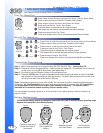
Blk/White (+/-) Dome Light Dome light supervision. See page 5.
Blk/White (+/-) Dome Light Dome light supervision. See page 5.
Orange (-) When Armed Negative output when system is armed.
Grey (-) Trunk Release Negative output for trunk release. 500ma max.
Yellow Ignition Input Input from vehicles ignition wire.
Black Ground Input System ground input.
Red Main Power Input Constant 12 Volt input.
14 Pin Connector
Green Door Lock Door Lock Output - Programmable - menu 1, setting 3.
Red 12 Volt Output Output for voltage inverter.
Blue Door Unlock Door Unlock Output - Programmable - menu 1, setting 3.
Low Current Only
Pink Second Unlock Second Unlock Output - Programmable - menu 1, setting 3
4 Pin Connector Red
2 Pin Connector Blue
2 Pin Connector Red
3 Pin Connector White
4 Pin Connector White
Second 4 Pin Connector White
Plug-in Program Button Connector.
The program Button is used to access the systems Programming Menu’s.
See page 5. for installation instructions.
Plug-in LED Connector.
See page 5. for installation instructions.
5
Green (-) When Disarmed Negative output when disarmed.
Pink Horn / Channel 5. Programmable - See menu 2, setting 7
Blue (+) Disconnect Triggers when 12volt circuit is broken.
Blue Sensor Full Warn Input trigger for addition alarm sensor(s)
Green Sensor Pre Warn Input trigger for addition alarm sensor(s)
Black Ground Output Ground output for addition alarm sensor(s)
Red 12 Volt Output 12 volt output for additional alarm sensor(s)
Satellite link connector.