


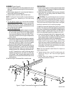

ASEMBLY (refer Figure 2)
1. Insert the wide leg (#13) into tube welded at the end of
boom (#1) and the narrow leg (#14) to boom exten-
sion (#2).
2. Slide transfer adapter (#11) over the end of boom ex-
tension (#2) with tube toward you.
3. Insert the boom extension (#2) into boom (#1).
NOTE: The Engine Transverse Bar may be used with or
without support arm, depending on the load being
supported.
4. To use without support arm: Secure both threaded
hooks (#3) to the tube welded on boom and transfer
adapter with barrel hex. nut (#7). Thread the hex. nut
(#7) all the way down towards the hook portion to hold
it out of the way until needed.
5. To use with support arm:
(a) Insert the adjustable leg (#6) to support arm (#10),
then hand tight with M8x65 bolt and wing nut (#9 &
8). Do not fully tighten wing nut as height adjust-
ment may be necessary once the Engine Trans-
verse Bar is placed over the engine compartment
of the vehicle.
(b) After determining the length of support arm needed,
Connect the support arm (#10) to transfer adapter
(#11) on the boom extension with M12x120 bolt
and wing nut (#5 & 4). Again, do not fully tighten
as some length adjustment may be required.
(c) Before placing the Engine Transverse Bar over the
engine compartment, install the two threaded
hooks (#3) povided. Insert one hook to the tube
welded on boom (#1) and secure with barrel hex.
nut (#7). Thread the hex. nut (#7) all the way down
towards the hook portion to hold it out of the way
until needed. Then, locate the best position on the
support arm for the second hook and install in the
same manner.
6. Now the Engine Transverse Bar is ready to use.
3
Atd7477-M0
OPERATION
1. Determine the location of the two engine support bolts
on your vehicle. Then place the Engine transverse bar
directly over these two bolts.
2. Adjust the boom extension (#2) to ensure that both
legs (#13 & 14) are sitting inside the fender of the
engine compartment.
! CAUTION: If the inside fender lips are more than
61" apart, the Engine Transverse Bar must not be used.
Do not extend past the designated marking (61") as over-
extending this unit may compromise the 700 lb. Capacity.
This could cause the Engine Support Bar to collapse,
resulting in personal injury or property damage.
3. Adjust to ensure the support arm (#10) is in correct
position. The rubber tip of the adjustable leg (#6) should
be on a flat, reinforced surface capable of supporting the
weight of engine. Tighten both wing nuts (#4 & 8) to
secure the adjustable leg (#6) and support arm (#10).
4. Lower the threaded hooks (#3) to appropriate posi-
tion. Ensure that the hooks are directly over the
engine support bolts or brackets; therefore the engine
does not swing when vehicle is disassembled.
5. Attach the looped ends of the two 1/8" braided steel
cables (#12) to the engine support bolts on the
engine and loop middle of braided cables over hooks.
If the engine being supported is equipped with engine
lift brackets, hook the hooks (#3) directly into engine
lift brackets for extra protection.
Note: Use only fasteners rated Grade 5 or higher as
engine support bolts.
6. Tighten the barrel hex. nuts (#7) on both hooks until
cables are snug or hex. nuts are tight against
support bar.
7. Double check that engine is properly supported
before disassemble the vehicle.
Figure 2 - Engine Transverse Bar Assembly & Parts Illustration