


3
ACCEL www.accel-ignition.com
arming cover plate over the switch. Note the align-
ment tab and slot on the arming cover plate and the
switch. Secure the switch and arming cover plate to
the switch with the switch nut.
Step #7
Carefully route the ACCEL harness away from any
linkage, air conditioning lines, heater hoses, exhaust
manifolds, etc. by using the mounting hardware
included in the kit.
Step #8
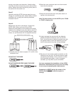
Measure the coil wire to the length. Connect the
ACCEL 300+ 8.8mm coil wire to the ACCEL
Afterburner switchable coil and measure the length
needed to the distributor cap, then add an extra 1/2"
to 1" to the length. Once the finished length is deter-
mined, cut and terminate with the supplied terminal.
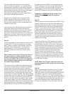
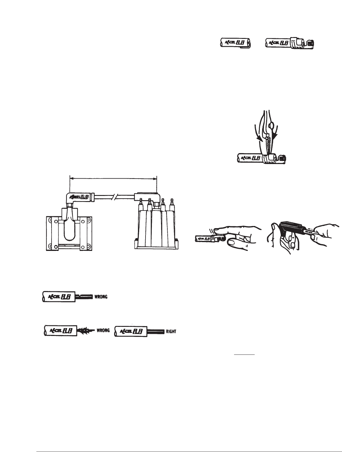
A) Carefully strip the wire to expose 1/2" to 5/8" of the
conductor core.
DO NOT SLIT THE CORE
DO NOT SHRED OR STRIP AWAY THE CORE
B) Bend the core conductor back over the wire and
insert into the terminal.
C) Bend the terminal tabs over with pliers and/or an
ignition wire-crimping tool.
Note: For best results, use the ACCEL p/n’s 170036
or 170037 crimping tool.
D) Lightly lubricate the terminal with the dielectric
grease included and slide the wire into the HEI
boot. A small amount of dielectric grease may also
be applied inside of both the distributor and coil
boot to help prevent any high voltage leakage.
E) Be sure you have made a good connection on the
distributor cap and coil. You should recheck these
connections periodically. If the connector in either
boot becomes grey-green in color or appears
corroded, you may have a poor connection.
You have completed the installation of the ACCEL
Afterburner switchable coil and you are now ready
to now enjoy increased ignition performance.
Remember to NEVER
switch the modes of the
ACCEL Afterburner coil while the engine is
running!
MEASURE WIRE TO CORRECT LENGTH