Assembly
23
MAN0869 (04/13/2011)
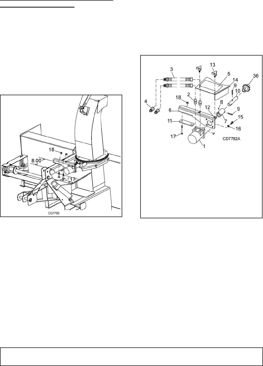
MOUNTING HYDRAULIC CHUTE ROTA-
TOR OPTION (FIGURE 22)
1. Fasten coupler (7) to hydraulic motor (1) using
woodruff key and set screw (8).
2. Fasten hydraulic motor assembly to hydraulic
motor mount bracket (6) using cap screws (15) and
lock washers (16).
3. Fasten hydraulic motor coupler (7) to shaft rotator
(10) using roll pin (9).
4. Fasten hydraulic motor mount to upper three-point
channel with cap screws (17), link (11), and hex
nuts (18).
Figure 21. Motor Mount Position 8" from Front
5. Remove rotator sprocket from lower hitch pin.
Position rotator sprocket in square opening on
chute adapter with hole facing towards hitch. Slide
hydraulic motor and channel assembly into rotator
sprocket and fasten using roll pin.
6. Fasten flow restrictors (2) to hydraulic motor.
7. Fasten hydraulic hose (3) to restrictors (2).
8. Fasten couplers (4) to ends of hoses (3).
Figure 22. Hydraulic Chute Rotator Installation
17. 3/8 NC x 4 HHCS
18. 3/8 NC Locknut
1. Hydraulic Motor
2. Restrictor
3. Hydraulic Hose
4. Coupler
5. Decal
6. Mounting Bracket
7. Coupler
8. Set Screw
9. Roll Pin
10. Shaft Rotator
11. Mounting Link
13. 3/8 x 3/4 crew
15. 3/8 NC x 1" HHCS
16. 3/8 Lock Washer
17. 3/8 NC x 4 HHCS
18. 3/8 NC Locknut
36. Rotator Sprocket
