Run a solid bead of sealant around the transition plate, making sure to cover each screw head. Be
careful not to get any sealant above the lip of the transition plate. See diagram of transition plate.
Cable Entry Plate Installation:
Decide the best location for the cables to enter the vehicle.
You will need to run:
A coax directly to each receiver location.
A control cable to the TRAV’LER Interface box.
Drill a 1/2” hole in the roof and push the required wires through. (Installations for multiple receivers may
require a larger hole or multiple holes as each receiver requires a dedicated coax cable.) Each receiver
will require at least one coax cable. See receiver manual for wiring details.
Place the cable entry plate supplied in hardware bag over the hole and cables. Screw the plate in place
and seal the plate and screw holes with approved sealant (not included).
Depending on the length of the cable on the roof, you may need to use cable clamps between the unit
and your cable entry plate. Clamping every 12-16” should eliminate any unnecessary cable movement.
FIGURE 4
LIP OF
TRANSITION
PLATE
DO NOT SEAL
SEAL
!
WARNING: DO NOT cut any
wires when you drill the hole
for your cables.
5
Winegard recommends in-
stalling the Accessory Detect
Cable, this can provide an
emergency stow function.
Rev. 4/15/08
INSTALLATION
FIGURE 5
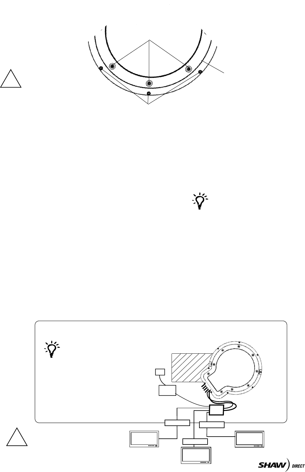
OVERALL INSTALLATION DRAWING
FRONT OF RV
PORTS
A - E and
POWER
POWER
SUPPLY
For best results, use TV
1 for the receiver that will
be most active.
ENTRY PLATE
!
The SK-7002 will support up to
four receivers.
TV 1
TV 2
TV 3
IDU
RECEIVER
RECEIVER
RECEIVER
GPS Installation:
The GPS antenna is connected to the TRAV’LER by a 6’ cable running to Port E on the TRAV’LER
Mount.Toinstallit,ndanopenareatoeithersideoftheTRAV’LERMountatleast18inchesfromthe
mount and place a small dot of sealant. Place the GPS antenna on the sealant and press it into place.
Secure any excess cable. WARNING: DO NOT CUT the GPS cable.


