11
Model 432
Important: To the Operator
Section 5 Important: To the Operator
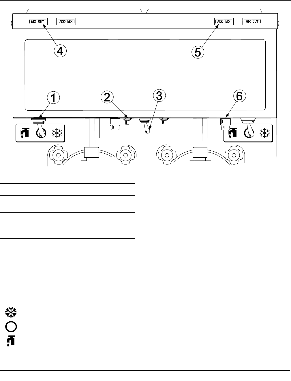
Figure 4
Item
Description
1 Switch- Toggle - 3 PDT
2 Switch- Push Button - SPST
3 Switch- Toggle- SPST - 3/4 HP/250 V
4 Light- Amber- Rect. - 12 VDC - MIX OUT
5 Light- Amber- R ect. - 12 VDC - ADD MIX
6 Viscosity Adjustment
The following chart identifies the symbol definitions
used on the operator switches.
= The “ON/AUTO” button.
= The “OFF” button.
= The “WASH” button.
Control Switch (Item 1)
The center position is “OFF”. The left position i s
“WASH”, which activates only the beater motor . The
right position is “AUTO”, which activates the beater
motor and the refrigeration system.
Push- Button Switch (Item 2)
If an overload condition occurs, the freezer will
automatically stop operating. To properly reset the
freezer, place the toggle switch in the “OFF” position.
W ait two o r three minutes; then press the push- button
switch. Place the power switch in the “W ASH” position
and observe the freezer’s performance. Place the
power switch in the “AUTO” position.
Note: If the freezer is unplugged from the wall
receptacle, it will be necessary to press the
push- button switch for the freezer to operate once
power is re- established.
Display Light Switch (Item 3)
The display light switch is located under the control
channel. The left position is “OFF”. The right position
is “ON”, and activates the display light.


