Publication 1771-6.5.132 - June 2000
Hardware Setup 3-7
Installing the 1771-SDN
Scanner Module
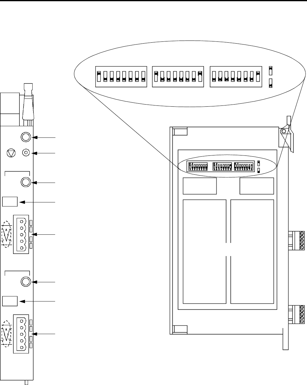
Refer to the following figure as you install the 1771-SDN module.
Module Status Indicator - indicates
whether the device has power and is
functioning properly.
MODULE
STATUS
RESET
CHANNEL 1
NETWORK
STATUS
NODE/
ERROR CODE
DeviceNet
CHANNEL 2
DeviceNet
NETWORK
STATUS
NODE/
ERROR CODE
Channel 1 Status Indicator - gives
diagnostic indications for Channel 1.
Node Address and Status Display -
displays numeric codes that indicate
scanner node address, status and/or
errors for Channel 1.
DeviceNet Port 1 - use the color-coded
header to wire your module.
Channel 2 Status Indicator - gives
diagnostic indications for Channel 2.
Node Address and Status Display -
displays numeric codes that indicate
scanner node address, status and/or
errors for Channel 2.
DeviceNet Port 2 - use the color-coded
header to wire your module.
Reset Button - resets your module.
= ON = 1
= OFF = 0
Multi-position Switches - use to set the data rate, chassis
addressing mode, and scanner node address for each channel.
Data Rate
Switch Settings
Chassis Address
Switch Settings
Channel 1 & 2
Node Address Switch Settings
Left Side of Module
= ON = 1
= OFF = 0
12345678
12345678 12345678
ON
ON
ON
Allen-Bradley
1771-SDN


