PFAM550
7
Rev. 07/03
Ph: 800-421-6511
www.picomacom.com
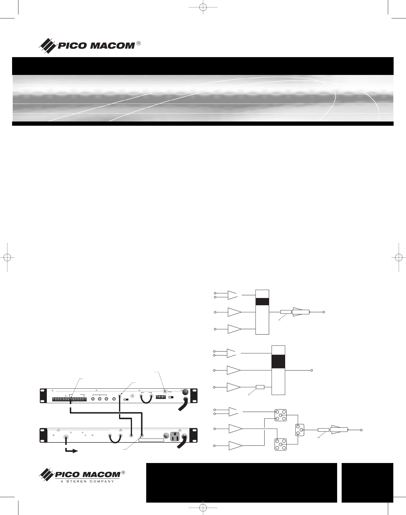
Installation Procedure
Signal Combining Methods
PICO MACOM recommends connecting the headend components in the
following manner: Each of the modulators, signal processors or strip ampli-
fiers output are connected to a combining network. Either a PHC-12G or
a PHC-24G headend combiner may be used to accomplish this purpose.
The PHC-12G or PHC-24G passive headend combiner consists of two
rows of directional couplers combined by a hybrid splitter. Normally, the
odd channels are combined on one row while even channels are combined
on the other row of directional couplers for maximum isolation. The output
of the combiners may be connected to the input of a launch amplifier such
as a CA-30RK550 or CA-30RK1000. The output of the amplifier is con-
nected to the main distribution line.
The CHC16U/550 and CHC16U/860 sixteen channel active combiners
provides both signal combining and post amplification of the headend
signals. Up to 16 channels may be combined using the CHC16U. The
combiner gain is 15 dB per channel.
A 24 channel system hook-up is shown. (The same combining result may
be accomplished by using a single PHC-24G).
The two PHC-12G outputs are combined via a two-way splitter, which is
connected to a CA-30RK1000 launch amplifier. The input levels to the
combiner, whether from a modulator, signal processor or a strip amplifier,
must be at the same amplitude.
Installation
It is recommended that assistance be available to safely install equipment in
equipment racks. Chassis must be fastened securely in equipment rack
before populating with modules.
1. Install chassis in equipment rack (equipment rack sold separately) by
supporting the bottom and rear of PFAM550 at the desired elevation
in rack.
2. Line up the side holes of chassis with the tapped equipment rack holes.
3. Insert the provided screws through the side holes in chassis and
thread into the tapped equipment rack holes.
4.Fasten the bottom screws first, then fasten top screws (tighten
securely).
5. Install a short F-type jumper cable (provided) between the IF output
and IF input connector on the rear of the PFAM550 (Required for
proper operation).
6. Connect a cable from the output of the video source to the video
input connector of the PFAM550.
7. Connect a cable from the output of the audio source to the audio
input connector of the PFAM550.
8. Connect a cable from the output RF connector of the PFAM550 to the
input of the combining system.
9. Remove the channel select access panel on the front of the
PFAM550.
10. Select the desired output channel by using a plastic screw driver to
set the DIP switches using the included chart.
11. Connect power cord to receptacle supplying uninterrupted line power
(LED on front panel will illuminate).
12. Connect a cable between the front panel output test point and a
spectrum analyzer or signal level meter. Measure the video and aural
carrier level.
13. Adjust the aural carrier level to 15dB below the level of the video
carrier by slowly rotating the VIDEO AUDIO RATIO adjustment on the
front panel of the PFAM550.
14. Connect a cable between the combining system test point and a
spectrum analyzer or signal level meter. Measure the video and aural
carrier level of the PFAM550 and adjacent channels.
15. Adjust the Output level of the PFAM550 to match the video and audio
carrier levels of adjacent channels by adjusting the OUTPUT LEVEL
adjustment on the front panel of the PFAM550.
h. 2
Ch. 2
Ch. 2
Ch. 3
Ch. 4
h.
h.
Ch. 4
Ch. 3