HOOKING UP THE TELEVISION
I
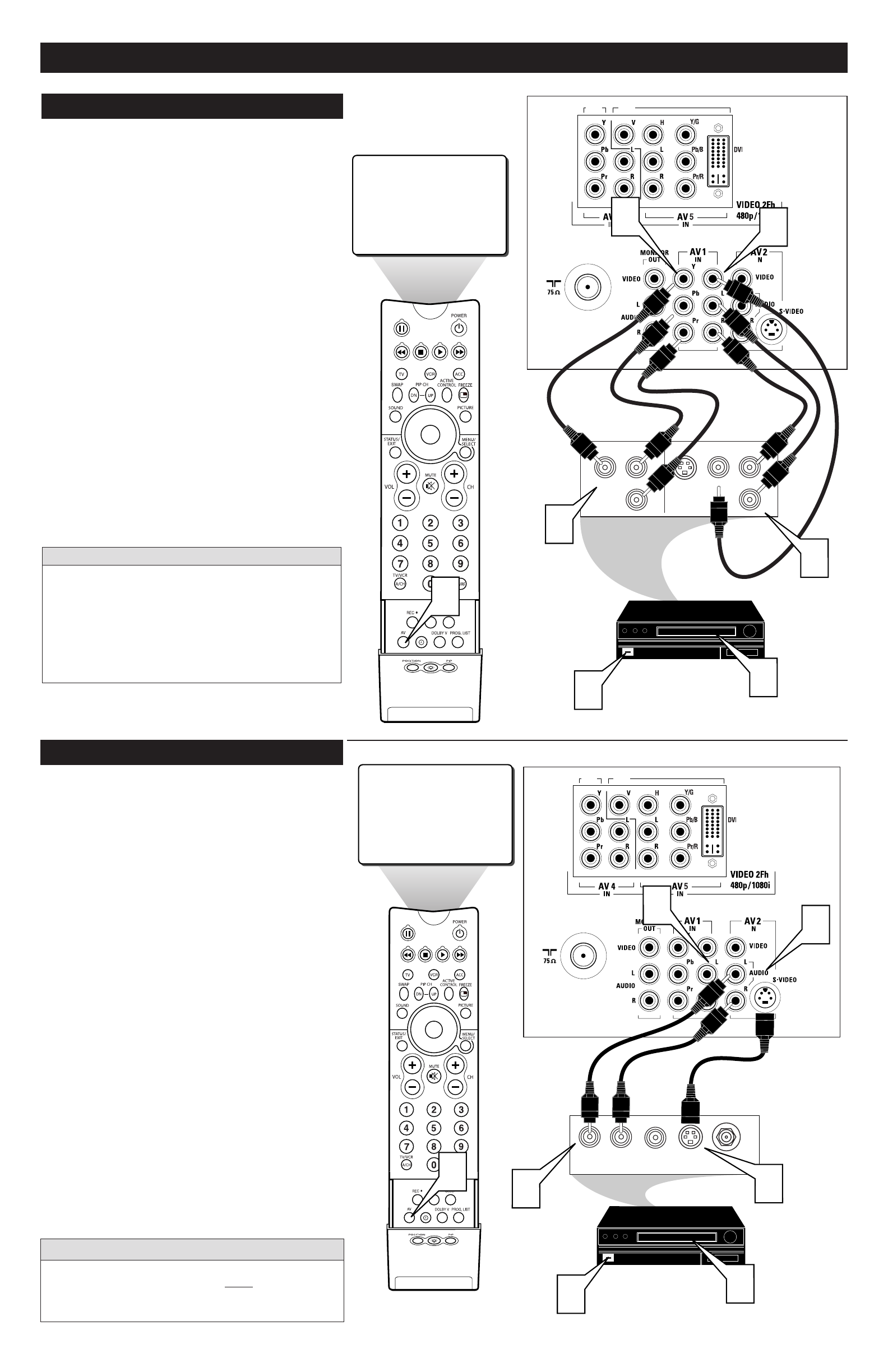
f using an accessory device that is not high definition but uses
Component Video jacks. The AV1 jacks on the TV offer the user
the possibility of better video reproduction using the Component
Video Inputs. The color difference signals (Pb, Pr) and the lumi-
nance (Y) signal are connected and received separately, which
allows for improved color bandwidth information (not possible
when using composite video or S-Video connections).
1
Connect the Component (Y, Pb, Pr) Video OUT jacks
from the DVD player (or similar device) to the (Y, Pb, Pr)
IN(put) jacks on the TV. When using the Component Video
Inputs, it is best not to connect a signal to the AV1 Video
Input.
2
Connect the yellow VIDEO CABLE along with the red
and white AUDIO CABLES to the AUDIO (left and
right) OUT(put) jacks on the rear of the accessory device
to the AV1 VIDEO and AUDIO IN(put) jacks on the TV.
3
Press the AV button on the remote control repeatedly to
tune to the CVI channel.
4
Turn the TV and the DVD (or digital accessory device)
ON.
5
Insert a DVD disc into the DVD player and press the
PLAY ᮣ button on the DVD Player (or digital accesso-
ry device).
HD1
HD2
S-VIDEO
OUT
OUT
OUT
L
R
AUDIO
VIDEO
COMP VIDEO
Y
Pb
Pr
2
1
4
5
CVI
3
1
2
COMPONENT VIDEO INPUT (CV1)
The description for the component video connectors may differ
depending on the DVD player or accessory digital source
equipment used (for example, Y, Pb, Pr; Y, B-Y, R-Y; Y, Cr,
Cb). Although abbreviations and terms may vary, the letters b
and r stand for the blue and red color component signal con-
nectors, and Y indicates the luminance signal. Refer to your
DVD or digital accessory owner’s manual for definitions and
connection details.
HELPFUL HINT
AUDIO IN
(RED/WHITE)
COMPONENT
VIDEO
CABLES
BACK OF TV
ACCESSORY DEVICE
EQUIPPED WITH
COMPONENT VIDEO
OUTPUTS.
VIDEO
(YELLOW)
CABLE
T
he S(uper)-Video connection on the rear of the TV can provide
you with better picture detail and clarity for the playback of
accessory sources such as DBS (digital broadcast satellite), DVD
(digital video discs), video games, and S-VHS VCR (video cas-
sette recorder) tapes than the normal antenna picture connec-
tions.
NOTE: The accessory device must have an S-VIDEO OUT(put)
jack in order for you to complete the connection on this page.
1
Connect the S-VIDEO CABLE to the S-VIDEO input jack
on the rear of the television.
2
Connect the AUDIO (red and white) cables to the AUDIO
AV2 IN jacks on the rear of the TV
.
3
Connect the S-VIDEO CABLE to the S-VIDEO
OUT(put) jack on the accessory device.
4
Connect the red and white AUDIO cables to the AUDIO
(left and right) OUT(put) jacks on the rear of the accessory
device.
5
Press the AV button on the remote control repeatedly to
tune the AV2 channel. The S-Video Input is dominate over
the AV2 Video Input.
6
Turn the VCR, DVD or other accessory device ON.
7
With the VCR (or accessory device) ON and a prerecorded
tape inserted, press the PLAY button to view the tape on
the television.
S-VIDEO INPUT
The S-Video jack and the AV 2 jacks work together. When a
device is connected to the S-Video jack, do not connect a signal to
the AV 2 IN Video jack. This could cause an over-lapping of two
video images on the TV screen.
cc
C
HECK IT OUT
HD1
HD2
AUDIO OUT
L R
S-VIDEO
OUT
ANT/CABLE
OUT
VIDEO
OUT
1
2
3
4
6
7
AV2
5
JACK PANEL
ON BACK OF TV
AUDIO CABLES
(Red & White)
S-VIDEO
CABLE
VCR or EXTERNAL
ACCESSORY DEVICE
WITH S-VIDEO OUTPUT
When using the S-Video Input, do not
connect a video signal to the AV 2 IN
Video Jack. This could cause a ghost
image to appear over the S-Video signal.
7


