Page 26
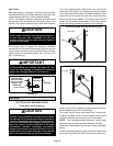
Before connecting the thermostat, check to make sure the
wires will be long enough for servicing at a later date. Make
sure that thermostat wire is long enough to facilitate future
removal of blower for service.
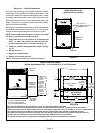
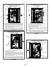
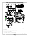
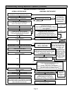
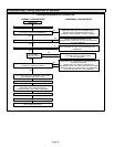
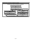
Complete the wiring connections to the equipment. Use the
provided unit wiring diagram and the field wiring diagram
shown in figure 33. Use 18−gauge wire or larger that is suit-
able for Class II rating for thermostat connections.
Electrically ground the unit according to local codes or, in
the absence of local codes, according to the current Na-
tional Electric Code (ANSI/NFPA No. 70). A green ground
wire is provided in the field make−up box.
NOTE − The ML180UH furnace contains electronic compo-
nents that are polarity sensitive. Make sure that the furnace
is wired correctly and is properly grounded.
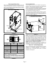
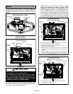
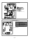
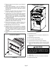
Accessory Terminals
One line voltage EAC" 1/4" spade terminal is provided on
the furnace integrated control. See figure 34 for integrated
control configuration. This terminal is energized when the
indoor blower is operating. Any accessory rated up to one
amp can be connected to this terminal with the neutral leg
of the circuit being connected to one of the provided neutral
terminals. If an accessory rated at greater than one amp is
connected to this terminal, it is necessary to use an exter-
nal relay.
One line voltage HUM" 1/4" spade terminal is provided on
the furnace integrated control. See figure 34 for integrated
control configuration. This terminal is energized in the
heating mode when the combustion air inducer is operat-
ing. Any humidifier rated up to one amp can be connected
to this terminal with the neutral leg of the circuit being con-
nected to one of the provided neutral terminals. If a humidi-
fier rated at greater than one amp is connected to this termi-
nal, it is necessary to use an external relay relay.
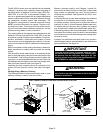
Generator Use − Voltage Requirements
The following requirements must be kept in mind when
specifying a generator for use with this equipment:
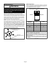
S The furnace requires 120 volts + 10% (Range: 108
volts to 132 volts).
S The furnace operates at 60 Hz +
5% (Range: 57 Hz to
63 Hz).
S The furnace integrated control requires both polarity
and proper ground. Both polarity and proper grounding
should be checked before attempting to operate the
furnace on either permanent or temporary power.
S Generator should have a wave form distortion of less
than 5% RHD.
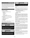
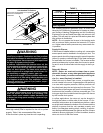
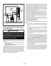
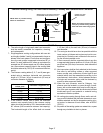
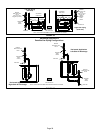
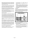
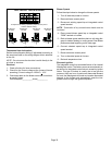
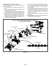
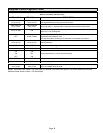
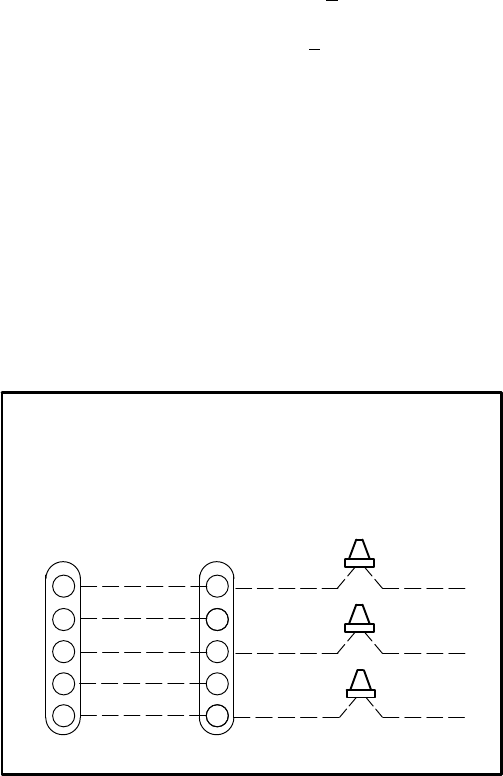
Thermostat
Install the room thermostat according to the instructions
provided with the thermostat. See figure 31 for thermostat
designations. If the furnace is being matched with a heat
pump, refer to the FM21 installation instruction or appropri-
ate dual fuel thermostat instructions.
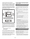
Thermostat Furnace Condensing
Unit
ML180UH and CONDENSING UNIT
THERMOSTAT DESIGNATIONS
(Refer to specific thermostat and outdoor unit.)
COMMON
POWER
HEAT
INDOOR BLOWER
Y
C
R
G
W1
Y
C
R
G
W
COOLING
FIGURE 31
CONDENSING
UNIT
CONDENSING
UNIT COMMON
*CONDENSING
UNIT
*NOTE − R" REQUIRED ON SOME OUTDOOR UNITS
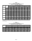
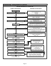
Indoor Blower Speeds
1 − When the thermostat is set to FAN ON," the indoor
blower will run continuously on the heating speed
when there is no cooling or heating demand.
2 − When the ML180UH is running in the heating mode,
the indoor blower will run on the heating speed.
3 − When there is a cooling demand, the indoor blower will
run on the cooling speed.