FOR THE PLUMBER
CONNECT TO WATER
(observe local codes)
1
Use l/o” OD soft copper tubing for the cold water
SUPPlY.
2P
‘d
rove e
a
convenient manual shut-off valve tn the
water lrne
3 Position the tubing so It can enter the access hole
located in the right-hand rear of the cabrnet. The
tubing should extend beyond the cabinet front
when the cabinet is pushed back into position. See
Figure 5.
NOTE:
Always purge the water line before making the final
connection to the inlet of the water valve to prevent
possible water valve malfunction.
After the cabinet is in place, bend the tubing to meet
the connection at the water valve. The garden hose
threaded compression fitting is found in the parts
bag. This joint provides a convenient disconnect for
service. Be sure the tubing is clear of compressor, to
prevent rattle.
CONNECT THE DRAIN
(observe local codes)
1 Th
e unrt IS provrded with a gravity drain
2 The ideal installation has a standpipe (1’14”
mrnimum) installed directly below the outlet of the
drawn tube. Refer lo Figure 5 for the proper location
of the standpipe.
3 It may be desirable to insulate drain line thoroughly
up to drain Inlet.
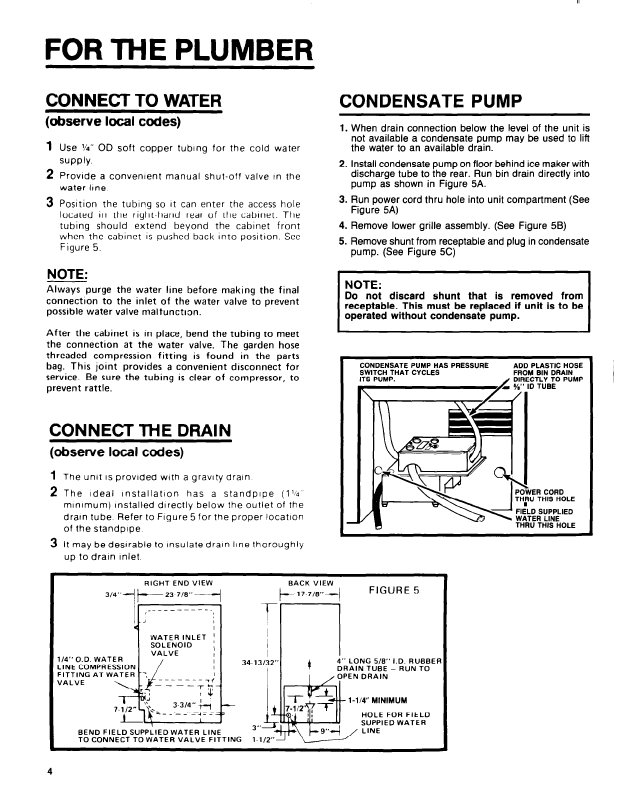
CONDENSATE PUMP
1. When drain connection below the level of the unit is
not available a condensate pump may be used to lift
the water to an available drain.
2. Install condensate pump on floor behind ice maker with
discharge tube to the rear. Run bin drain directly into
pump as shown in Figure 5A.
3. Run power cord thru hole into unit compartment (See
Figure 5A)
4. Remove lower grille assembly. (See Figure 5B)
5. Remove shunt from receptable and plug in condensate
pump. (See Figure 5C)
NOTE:
Do not discard shunt that is removed from
receptable. This must be replaced if unit is to be
operated without condensate pump.
CONDENSATEPUMPHASPRESSURE ADD PLASTIC HOSE
SWITCH THAT CYCLES FROM BIN DRAIN
ITS PUMP.
/
DIRECTLY TO PUMP
a %” ID TUBE
R CORD
THIS HOLE
SUPPLIED
R LINE
THIS HOLE
RIGHT END VIEW
BACK VIEW
FIGURE 5
I /
VALVE
1/4”O.D. WATER
LINE COMPRESSION
FITTING AT WATER
------I<
VALVE
BEND FIELD SUPPLIED WATER LINE
4
4” LONG 5/0” I.D. RUBBEF
DRAIN TUBE - RUN TO
I
, OPEN DRAIN
l-1/4” MINIMUM
HOLE FOR FIELD
3”
SUPPIED WATER
TO CONNECT TO WATER VALVE FITTING
/


