4
NOTE: Pump should be thoroughly flushed prior to disas-
sembly.
Motor/Gear Assembly Removal (Refer to exploded
view of pump)
1. If possible, position pump with sight caps (item 30) down.
2. Remove four screws (item 20) and lift out motor/gear
assembly.
3. Drain oil from pump if additional maintenance to pump
is required.
Gear Assembly Replacement
1. Remove six screws (item 25) and pull gear assembly
(item24) from motor.
2. Pull drive gear (item 27) and key (item 28) from motor
shaft.
DO NOT DISASSEMBLE GEAR ASSEMBLY.DO NOT DISASSEMBLE GEAR ASSEMBLY.
DO NOT DISASSEMBLE GEAR ASSEMBLY.DO NOT DISASSEMBLE GEAR ASSEMBLY.
DO NOT DISASSEMBLE GEAR ASSEMBLY. Planet
gears and ring gear are marked for proper assembly and must
not be altered.
Diaphragm Assembly/
Check Valve Replacement
NOTE: Diaphragm and check valve assemblies can be ser-
viced without removing motor and oil from pump body by
removing one at a time with diaphragm facing up. Care must
be taken not to contaminate oil.
1. Loosen cover (item 4) screws (item 20) slightly and drain
fluid trapped in the pumping chamber. Then remove
screws and covers.
2. Remove retainer screws (item 11) and o-rings (item 42).
3. Remove diaphragm assemblies (items 7, 8, 9 and 10) by
pulling check valves out of pump body, starting with outlet
valves first (item 9 at top of pump).
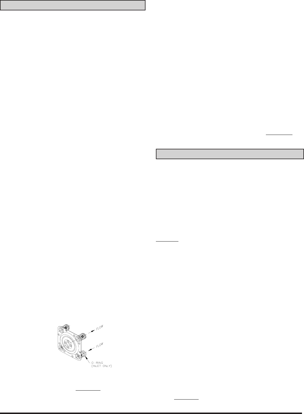
4. Install new diaphragm/check valve assembly, noting ball
location in relation to flow. O-rings are on inlet valves at
bottom of pump. Lubricate O-rings before inserting into
pump body. See Figure #1.
5. Insert four screws (item 11) and o-rings (item 42) into
diaphragm as shown and tighten to 35 in. lbs. of torque.
6. Install pump covers (item 4). Hand start and tighten screws
(item 20) to 50 in. lbs.
7. Install motor (item 1) and gear assembly (item 24). Be
sure gasket (item 26) is in place. Rotate motor until drive
shaft slips in hole in gear assembly. Tighten screws (item
20) to 50 in. lbs. of torque.
8 Fill with approximately 16 ounces of automotive grade
SAE 30W oil through one of the holes for sight caps (item
30).
To further disassemble pump.
9 Remove motor and drain oil, if complete disassembly is
required.
10.Remove four screws (item 19) and lockwashers (item 21)
holding bearing plate (item 17).
11.Remove bearing plate (item 17) and thrust plate (item 16).
12.Remove drive shaft (item 13), bearing (item 14), bearing
ring (15) and yoke assembly (item 12).
Assemble in reverse order. See step #4 through step #8
above for additional assembly instructions.
Hand start and
tighten screws to 50 in. lbs.
To keep pump running at its best, periodically perform the
following procedures. (Refer to exploded view drawing of
pump)
Chemical Applications
Do not allow chemical to remain in the pump for any extended
period of time, whereby the chemicals are allowed to “dry out.”
Thoroughly rinse pump and meter by flushing the pump with
water or appropriate flushing fluid.
DO NOT USE PRESSURIZED WATER OR PRESSURIZED
AIR
to flush your pump. Damage to the equipment can occur
if flush water pressure exceeds 15psi (1 bar). Instead, sub-
merge the suction tube or inlet adapter in clean water and
dispense water by operating the pump. Dispose of the flush
water properly. After flushing, pump air to remove as much
water as possible.
All Applications on annual basis or as needed.
1. Tighten all external screws to 50 in. lbs. (items 19, 20, & 23).
NOTE: NEVER EXCEED 50 IN. LB. TORQUE WHEN
TIGHTENING SCREWS.
2. Drain oil through sight caps and replace oil with
approximately 16 ounces of automotive grade SAE 30W
through one of the sight cap holes. The oil level should be
level with the bottom edge of the sight caps (item 30)
located on the front of the pump body.
NOTE: Always check oil level when the pump is level.
3. Check the four #10-24 x 1/2" machine screws (item 11)
holding the diaphragm in place. If loose, tighten screws to
35 in. lbs. to prevent internal leakage.
NOTE: If external screws (items 19, 20, & 23) are removed,
hand start and tighten to 50 in. lbs.
Figure #1
ASSEMBLY/DISASSEMBLY
MAINTENANCE


