Chapter 3 • Operating the System 5cr
Extron • System 5
cr
Switcher • User’s Manual
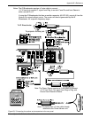
________ As stated earlier, each input button can be programmed to “learn” an
associated IR command. For example, selecting the PC1 input could also
send a signal to the projector to switch to its computer input mode, and
selecting VID1 could cause the projector to switch to S-video mode, etc.
3
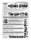
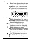
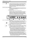
PC Input Selection Buttons and Indicators:
• PC1 – Input select button for computer video and audio. This selects the
input from the VGA and Audio connectors on the System 5 front panel.
• PC2 – Input select button for an RGBS or RGBHV source (and audio)
from the PC2 section of the rear panel. This could be from a computer,
through a computer-video interface.
• PC3 – Same as PC2 but input is from the PC3 section of the rear panel.
4
Composite or S-video inputs (VCR, DVD, etc.):
VID1 – 1st input select button for Composite Video or S-video with audio.
VID2 – 2nd input select button for Composite Video or S-video with audio.
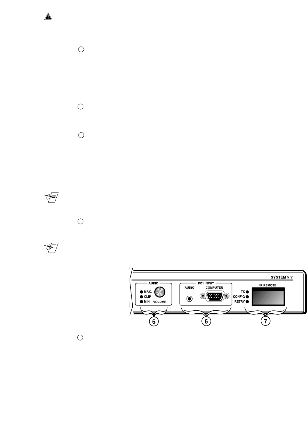
5
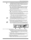
Audio Gain (Volume) Control knob for amplified output.
Max LED (red) – lights when the audio output level control has reached its
maximum point. This does not indicate the audio level.
Clip LED – lights when the output level is beginning to overdrive (peak).
This indicator is used to set the audio attenuation for the inputs.
Min LED – lights when the output level control has reached its minimum
point. This does not indicate the audio level.
_______ When all audio inputs are at the same level coming into the System 5
cr
,
the Volume knob functions as the master volume control for both audio
outputs. (See Setup Mode procedures later in this chapter.)
6
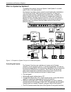
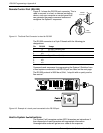
PC1 Input connectors – Audio and Computer VGA connectors selected
by the PC1 button. Connect a VGA cable to the 15-pin HD connector.
Plug the computer’s audio output to the audio jack.
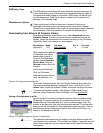
_______ Each of the controls described above are duplicated on the IR 40 remote
control, on the optional SCP 100 panels, and on the Windows® control
software. The operation is the same, including associated IR commands.
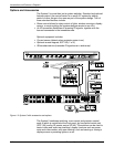
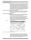
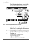
Figure 3-1b. Front panel controls and indicators
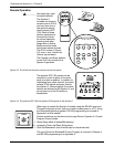
7
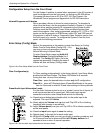
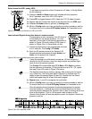
IR Function LEDs and Infrared Receiver/Learner Port – In addition to
each LED having its function, in combinations they indicate other things.
TX LED (green) – lights when System 5 is transmitting infrared signals.
Flashes with Config and Retry LEDs to indicate a time-out condition
for the configuration mode.
Config LED (amber) – When steady on the System 5 is in setup mode and
is ready to be configured. See the Setup Mode procedures for ways in
which this indicator is used in combination with other LEDs.
Retry LED (red) – Indicates the System 5 has failed to recognize a command
in the infrared learning process.
IR Remote – window receives signals from the IR 40 for normal operation, as
well as from other remote control sources when learning commands.
3-2