MN42-en-GB_v1.3 04/15
6
RESISTANCE MEASUREMENTS
WARNING: To avoid electric shock, disconnect power to the unit under test and discharge all
capacitors before taking any resistance measurements.
1. Set the function switch to the highest position.
2. Insert the black test lead banana plug into the negative COM
jack.
Insert the red test lead banana plug into the positive jack.
3. Touch the test probe tips across the circuit or part under test. It
is best to disconnect one side of the part under test so the rest
of the circuit will not interfere with the resistance reading.
4. Read the resistance in the display. Move the function switch to
the lowest position that is greater than the anticipated
resistance.
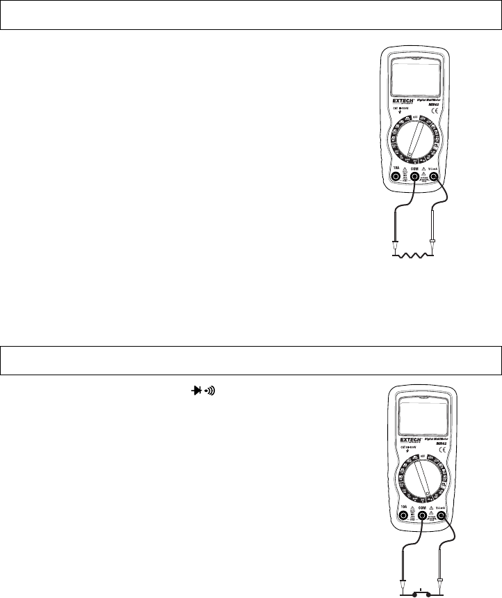
CONTINUITY CHECK
WARNING: To avoid electric shock, never measure continuity on circuits that have a voltage
potential.
1. Set the function switch to the position.
2. Insert the black lead banana plug into the negative COM jack.
Insert the red test lead banana plug into the positive jack.
3. Touch the test probe tips to the circuit or wire you wish to check.
4. If the resistance is less than approximately 30, the audible signal
will sound. If the circuit is open, the display will indicate “1”.


