T440 Users manual V021/B, © JED Microprocessors Pty Ltd Nov 17th 2008 Page 15
NEC projector families: GT60, HT,LT, LT30, NP40, LT60, LT80, MT70, NP1000,
NP4000, WT, VT, (38,400 baud, Code 10 hex)
NEC projector families: VT70, VT80, VT90 (19,200 baud, Code 11 hex)
NEC old or at 9,600 baud (eg with long cable runs): Code 12 hex
Note: Check the projector installation guide/user manual and set hex code to match projector speed.
In the back of each “Installation Guide” is a list of typical channel selection messages.
Also, see master NEC code list at: http://www.nec-display-solutions.co.uk/c/g/uk/en/Service/Home/index.html
Channel codes are:
Computer1 := 02 + 03 + 00 + 00 + 02 + 01 + 01 + 09; // RGB 1 VGA analog-RGB
Computer2 := 02 + 03 + 00 + 00 + 02 + 01 + 02 + 0A; // RGB 2 sometimes DVI analog
Computer3 := 02 + 03 + 00 + 00 + 02 + 01 + 03 + 0B; // DVI Analog
Computer4 := 02 + 03 + 00 + 00 + 02 + 01 + 1A + 22; // **DVI Digital OR component (VT770)
Computer5 := 02 + 03 + 00 + 00 + 02 + 01 + 1F + 27; // Input Select Viewer
Computer6 := 02 + 03 + 00 + 00 + 02 + 01 + 20 + 28; // LAN
Video1 := 02 + 03 + 00 + 00 + 02 + 01 + 06 + 0E; // Comp Video
Video2 := 02 + 03 + 00 + 00 + 02 + 01 + 0B + 13; // S-Video
Video3 := 02 + 03 + 00 + 00 + 02 + 01 + 07 + 0F; // Comp Video 2
Video4 := 02 + 03 + 00 + 00 + 02 + 01 + 0C + 14; // S-Video 2
Video5 := 02 + 03 + 00 + 00 + 02 + 01 + 10 + 18; // Component #1
Video6 := 02 + 03 + 00 + 00 + 02 + 01 + 11 + 19; // Component #2
Video7 := 02 + 03 + 00 + 00 + 02 + 01 + 12 + 1A; // Component #3
Video8 := 02 + 03 + 00 + 00 + 02 + 01 + 1A + 22; // **DVI Digital OR component (VT770)
Video9 := 02 + 03 + 00 + 00 + 02 + 01 + 24 + 2C; // Slot1-1 GT5000/6000
Video10 := 02 + 03 + 00 + 00 + 02 + 01 + 25 + 2D; // Slot1-2 GT5000/6000
Video11 := 02 + 03 + 00 + 00 + 02 + 01 + 29 + 31; // Slot2-1 GT5000/6000
Video12 := 02 + 03 + 00 + 00 + 02 + 01 + 2A + 32; // Slot2-2 GT5000/6000
Any one of these codes can be set into Constant:0/Constant:1 for computer codes and Constant:2/Constant:3 for video
codes. (The default is to have Computer1 (above) as the “Computer” channel and Video1 as the “Video” channel.
Setting OPT1 switch ON will swap Video1 and Video2 channels, making S-Video the video default.)
• OPT7 handshake mode and power on panel connection blink codes available.
Models HT410/510, LT180, VT70 series, and NP40 series don’t control audio via RS232: use a T461 instead.
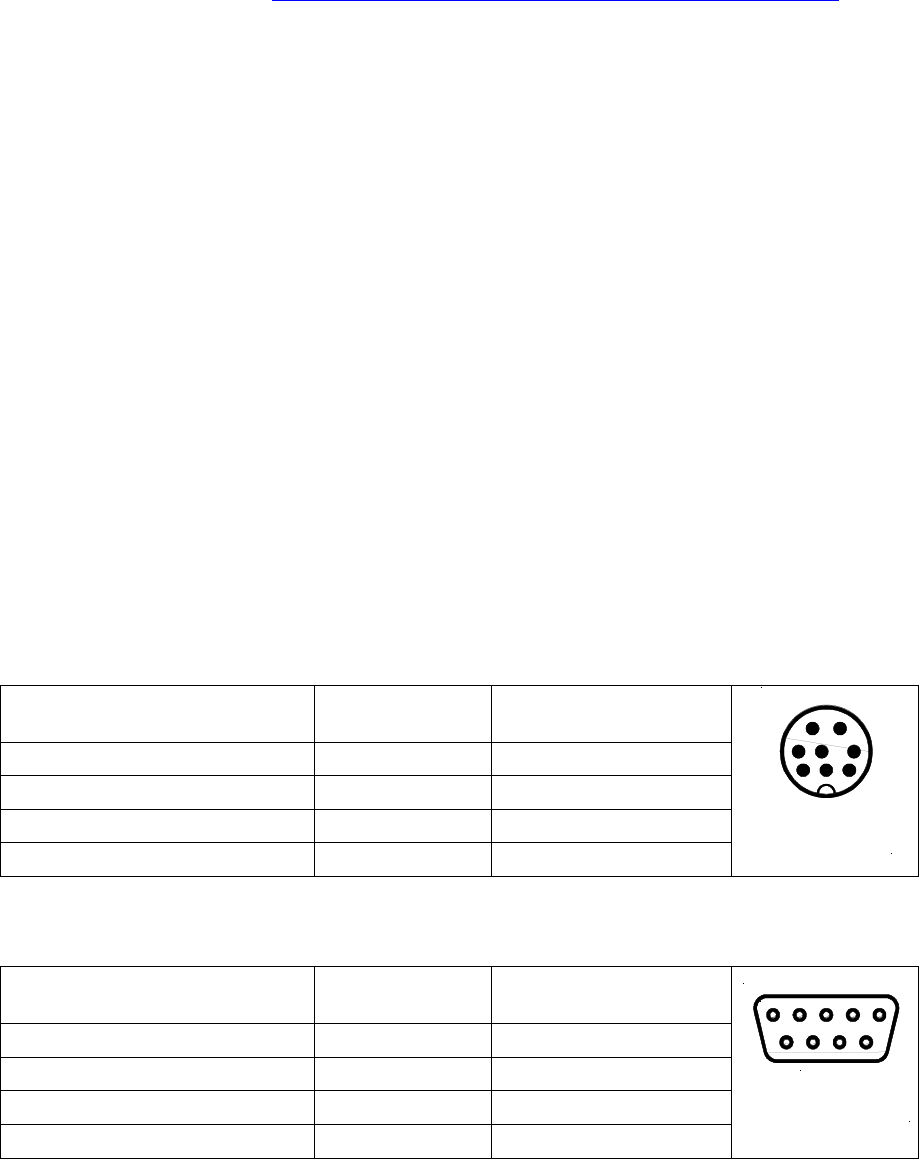
RS232 connections to NEC projectors
Most use a male 8-pin mini-DIN. Others, see D9 below.
Function/Direction T440 “projector”
Connection
“Serial” Port Connector
Ground Ground 8-pin mini-DIN pin 4
Data from T440 to projector Tx 8-pin mini-DIN pin 1 RXD)
Reply data from projector to T440 Rx 8-pin mini-DIN pin 7 TXD)
Plus 9 volt CTS/DTR to projector N/C N/C
Mini-DIN 8
solder side
43 5
1 2
6 7 8
After installation wiring of any projector to a T440, use a multimeter to check voltages of –9 on BOTH TX and RX pins
in any installation, as described in the troubleshooting part of this manual.
These use a 9-pin-D9 male on the projector, female on cable.
Function/Direction T440 “projector”
Connection
“Serial” Port Connector
Ground Ground 9-pin D-sub pin 5
Data from T440 to projector Tx 9-pin D-sub pin 2 (RXD)
Reply data from projector to T440 Rx 9-pin D-sub pin 3 (TXD)
Plus 9 volt CTS/DTR to projector “RTS” 9-pin D-sub pin 8(CTS IN)
8
1 2 3 4 5
6 7 9
D-sub 9 female
solder side


