Reference Manual
MAN-0081, Revision 4 July 2014
7
Section 3: Terminal board configurations
There are multiple terminal board configurations facilitated by the JB series junction box. This allows
effective, safe, and accurate terminations and sensor separation requirements across the Net Safety
product line. These configurations are outlined below.
Each model of the multi-purpose junction box contains a PCB with different components for features
that are applicable to specific models of Net Safety products, such as meter test jacks or a magnetic
switch. Please refer to the specific transmitter, detector, or sensor manuals for detailed instructions
about using these options.
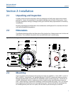
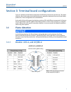
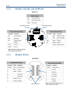
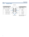
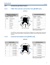
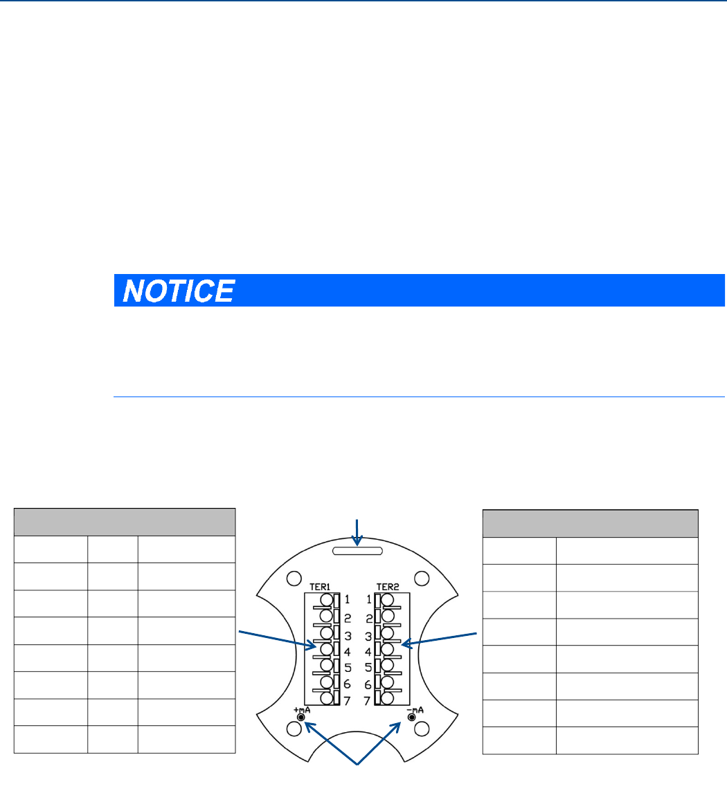
3.1 Flame detection
In the following drawings, the f
lame detector wiring side refers to wiring between the flame
etector and the junction box terminals. Panel/PLC/DCS/RTU wiring side refers to wiring between
power source and the junction box. Wiring should be done according to the designated terminal
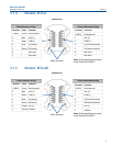
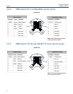
3.1.1 Models: UVS-A, and UV/IRS-A
MVI test switch (JB-MPS only)
JB-MPS-A/S or JB-MPNS-A/S
Note: Shield should be terminated
at the Panel/PLC/DCS/RTU