BI-DIRECTIONAL TRAVEL STOP INSTRUCTION
Bradford Actuators feature bi-directional pinion
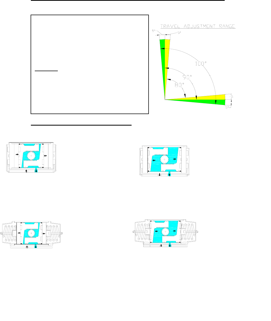
travel stops. Stops located on the side of the
actuator allow a full ±5˚ of valve travel adjustment,
giving a guaranteed range of adjustment between
80˚ and 100˚ of actuator travel. These travel stops
are designed to absorb the maximum rated torque of
the actuator and the maximum impact loading
associated with recommended stroke speed.
Operation
Adjustment of the counterclockwise and clockwise
rotation limits are accomplished by turning the
respective left and right stop adjustment screws to
increase or reduce the output rotation angle.
ACTUATOR OPERATION
Double-Acting (Top View)
P1P2
P1P2
For a counter-clockwise output,
apply pressure to P1. This
forces the pistons to move away
from the center resulting in the
linear piston travel converted to
counter-clockwise rotation of
the pinion. The air volume
outside each piston is exhausted
at P2.
For a clockwise output, apply
pressure to P2. This forces
the pistons to move to the
center resulting in the linear
piston travel converted to
clockwise rotation of the
pinion. The air volume
between the pistons is
exhausted at P1.
Spring Return (Top View)
P2 P1
P1P2
For a clockwise output, the
spring energy forces the
pistons to move to the
center resulting in the
linear piston travel
converted to clockwise
rotation of the pinion. The
air volume between the
pistons is exhausted at P1,
while the volume outside
the pistons is vented at P2.
For a counter-clockwise
output, apply pressure to
P1. This forces the pistons
to move away from the
center, compressing the
spring sets, and resulting in
the linear piston travel
converted to counter-
clockwise rotation of the
pinion. The air volume
outside each piston is
exhausted at P2.
NOTE: When Reverse Rotation is required, the pistons can be inverted in the housing.
This will result in a clockwise rotation when pressure is applied to P1 and a counter-
clockwise rotation when P1 is vented.


