724-746-5500 | blackbox.com
Page 13
Chapter 4: Installing the Switch
4. Installing the Switch
4.1 Selecting a Site
NOTE: The switch can be mounted in a standard 19-inch equipment rack (via the included rackmount kit). Follow the guidelines
below when choosing a location.
The site should:
• Be located at the center of all the devices you want to link and near a power outlet.
• Be able to maintain its temperature within 32 to 140° F (0 to 60° C) and its humidity within 10% to 90%, non-condensing.
• Be accessible for installing cabling and maintaining the devices.
• Allow the status LEDs to be clearly visible.
NOTES:
Make sure the twisted-pair Ethernet cable is always routed away from power lines, radios, transmitters, or any other electrical
interference.
Make sure that the switch is connected to a separate grounded power outlet.
4.2 Ethernet Cabling
To ensure proper operation when installing the switch into a network, make sure that the current cables are suitable for
100BASE-TX or 1000BASE-T operation. Check the following criteria against the current installation of your network:
• Cable type: Unshielded twisted pair (UTP) or shielded twisted pair (STP) cable with RJ-45 connectors. We recommend Category
5 or Category 5e with a maximum length of 328 feet (100 meters) for 100BASE-TX, and Category 5e or 6 with a maximum
length of 328 feet (100 meters) for 1000BASE-T.
• Protection from radio frequency interference emissions.
• Electrical surge suppression.
• Separation of electrical wires and data based network wiring.
• Safe connections with no damaged cables, connectors, or shields.
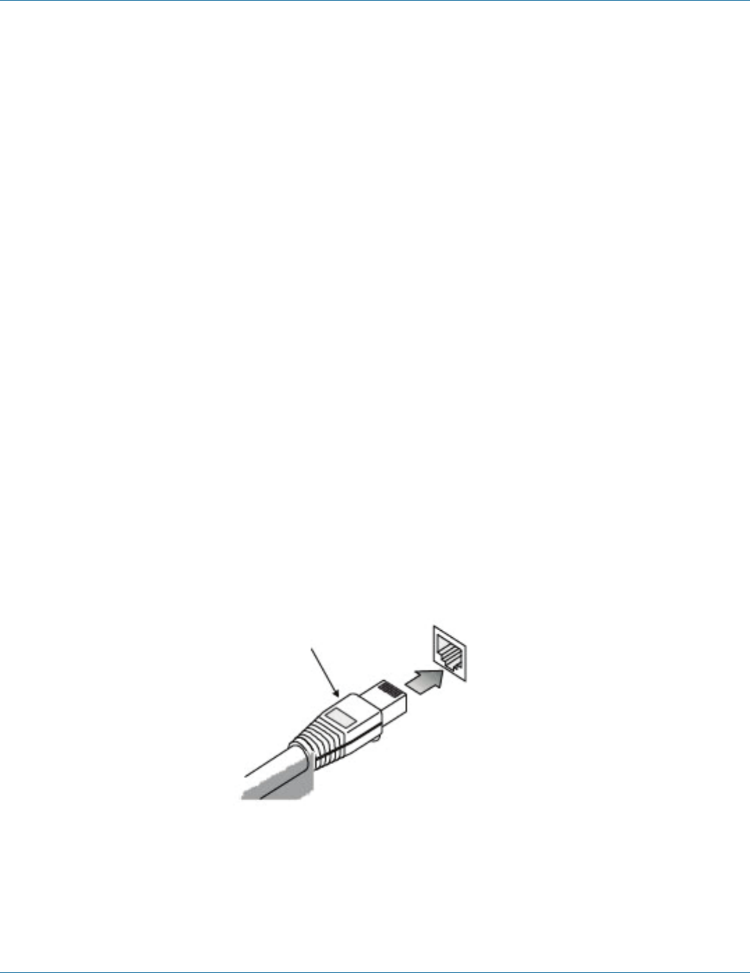
Figure 4-1. RJ-45 connections.


