3
! WARNING
• Study, understand, and follow all printed
materials provided with/on this product before use.
• Do not exceed rated capacity.
• This is a lifting device only!
• Immediately after lifting, support the load with
a pair of appropriately rated jack stands.
• Use only on hard, level surface.
• Do not use adapters or accessories that are not
provided initially.
• Lift only on areas of the vehicle as specied by
the vehicle manufacturer.
• Never wire, clamp or otherwise disable the lift
control valve to function by other than operator's
hand.
• No alterations shall be made to this product.
• Failure to heed these markings may result in
personal injury and/or property damage.
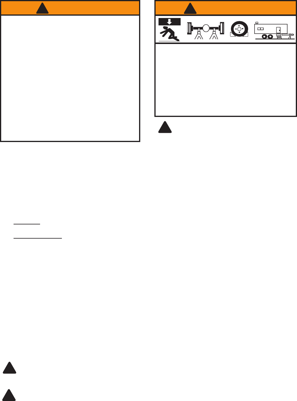
To avoid crushing and related injuries:
•
Never work on, under or around a load supported
only by hydraulic jack.
•
Always use adequately rated jack stands.
• Chock each unlifted tire in both directions.
• Do not use this device to lift, level, lower, support nor
move a house, mobile home, travel trailer, camper or
any building structure.
• Be alert and sober when using this product. Do not
operate under the inuence of drugs or alcohol.
! WARNING
X
!
Be sure all tools and personnel are clear
before lowering load. Only attachments and/or
adapters supplied by the manufacturer shall be used.
Lift only on areas of the vehicle as specied by the
vehicle manufacturer.
PREPARATION
Before Use
1.
Verify that the product and application are compatible, if in doubt call ATD Technical Service (636) 327-9050.
2. Before using this product, read the operator's manual completely and familiarize yourself thoroughly with the
product, its components and recognize the hazards associated with its use.
3. Assemble handle, ensure spring clips align with slots.
4. To familiarize yourself with basic operation, use the notched end of provided handle to engage and turn the release
valve:
a. Clockwise until rm resistance is felt to further turning. This is the ‘CLOSED’ release valve position used to
raise the ram plunger.
b. Counter-clockwise, but no more than 1 turn from the closed position. This is the ‘OPEN’ release valve
position used to lower the ram plunger.
5. With ram fully retracted, locate and remove the oil ller plug/screw. Insert the handle into the handle sleeve, then
pump 6 to 8 strokes. Ensure the oil level is just below the oil ller hole. Reinstall the oil ller plug/screw.
6. Pour a teaspoon of good quality, air tool lubricant into the air supply inlet of the lift control valve. Connect to air
supply and squeeze lift control valve for 3 seconds to evenly distribute lubricant.
7. This product is equipped with the popular 1/4" NPT air coupler. When installing a different air coupler of your
choice, ensure that thread tape or compound is used when servicing connections. To ensure dependable, trouble
free operation an inline air dryer and oiler is recommended.
8. Check that the pump operates smoothly and that the extension screw will thread up/down easily before putting
into service. Replace worn or damaged parts and assemblies with ATD authorized replacement parts only.
Bleeding / Venting Trapped Air
With the release valve in the OPEN position (4b above) and with ram plunger fully lowered, locate and remove the
oil ller plug/screw. Insert the handle into the handle sleeve; then pump 6 to 8 full strokes. This will help release any
pressurized air which may be trapped within the reservoir. Oil level should be even with the bottom of the oil ller
hole. Reinstall the oil ller plug/screw.
Use only handle provided by jack manufacturer. The handle provided with this jack will safely engage the
release valve and operate the handle sleeve. If handle is worn, operates abnormally, or will not positively
engage the release valve, STOP, discontinue use of the jack until a factory replacement handle can be acquired.
!
Paint contains lead! DO NOT sand or grind painted surface!
!


