5
1) Determine the position of the last outlet header hold-
down bracket for the row of collectors. Mark this point on the
roof. The collector outlet headers will be located approxi-
mately 1” (25mm) below this mark. Refer to Figure 3.
2) Using this point, snap a chalk line to the opposite end
of the row. This line would slope down the roof toward the
inlet approximately 1” (25mm) for each six (6) collectors in
the row. Drill a hole for the first outlet header bracket on
the first roof mark. Measure 51” (1.3m) further along the
chalk line, mark, and drill a second hole. Use a 3/16”
(5mm) drill for 5/16” (8mm) diameter screws. Then con-
tinue drilling pilot holes all along the chalkline for the total
number of collectors which you are using for the job.
3) Inject a generous amount of high quality sealant into
each hole and onto the surrounding roof surface. Bolt all
the outlet header hold down brackets to the roof as
shown in Figure 4.
4) Locate the hold-down strap bracket holes using the
information in Fig. 1, Table A. Measuring from the top
outlet header bracket chalk line, snap another chalk line
parallel to this line using the “A” dimension. The “B”
dimension is the same for all collector sizes, which is 16”
(40cm) up from the outside of the bottom header and can
be measured after the collectors are installed. Wait to
install the hold-down strap brackets until after the collec-
tors are installed so as not to damage the collectors
when you are bringing them to the roof for installation.
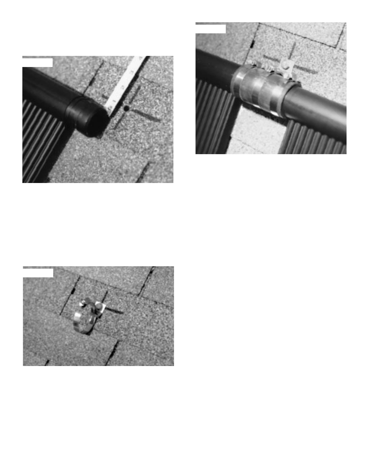
5) Bring the first collector to the roof and slip the proper
hoses over both ends of the inlet and outlet headers on
the last return collector. Make sure that the side of the
collector with the serial number label on it is facing down.
The long hoses go on the outlet of the last collector and
the inlet of the first collector. Push UP TO the hose locat-
ing shoulder, but NOT OVER it. Locate a hose clamp
3/8” (10mm) from the end of the hose in order to center it
on the header groove. This clamp must face up so as to
be accessible for tightening and will not rub against the
mounting surface. Make sure you securely tighten each
clamp with a nutdriver. If a nutdriver is not available, a
‘hex’ wrench or screwdriver will suffice. THE HOSE
CLAMPS MUST BE LOCATED OVER THE GROOVES
IN THE HEADER.
6) Position the collector on the roof so that the center of
the outlet connection hoses are directly beneath the
secured outlet header brackets and slip the bracket hold-
down clamps over the connection hoses. Lightly tighten
the clamp around the header hose. Refer to Figure 5.
Continue to install all the collectors in the array, coupling
them side to side.
Figure 5
Figure 3
Figure 4


