VACUUM RELIEF VALVE
Note: This end of row lower than
opposite end. See instruction 2.
FLOW
INLET
(from pool)
OUTLET
(to pool)
FLOW
END
CAP
INLET OUTLET
VACUUM
RELIEF
VALVE
PIPE
ADAPTOR
HOSE
3/4 HEIGHT
FROM POOL
TO UPPER
HEADER
ALTERNATE VACUUM
RELIEF VALVE LOCATION
INLET
(from pool)
OUTLET
(to return)
(130 cm)
51"
(130 cm)
51"
(130 cm)
51"
SEE TABLE B
SEE TABLE A
PANEL
PANEL
CENTERLINE
PIPE
ADAPTOR
SHORT
HOSE
(130 cm)
51"
(130 cm)
51"
SHORT
HOSE
(130 cm)
51"
LONG HOSE
OUTLET HEADERS
VACUUM
RELIEF
VALVE
SHORT
HOSE
BRACKET
BRACKET
LONG
HOSE
PIPE
ADAPTOR
ABSORBER
PLATE
HOSE
CLAMP
CENTERLINE
OF CLAMP
AND HOSE
HEADER
SEALING
GROVE
HOSE
LOCATING
SHOULDER
OPTIONAL
HEADER
INSERT
HEADER
3/8" (10mm)
HOLD-DOWN CLAMP
3/8" (10mm)
3 3/4" HOSE
OUTLET HEADER HOLD-DOWN BRACKET
4
Header Inserts (Part #50055-1 for
1 1/2”; #50055-2 for 2”) are used
in special situations where
unusually high stagnation
temperatures are expected,
such as in a desert climate
or where abnormally high
system pressures may occur.
Use four (4) inserts per collector.
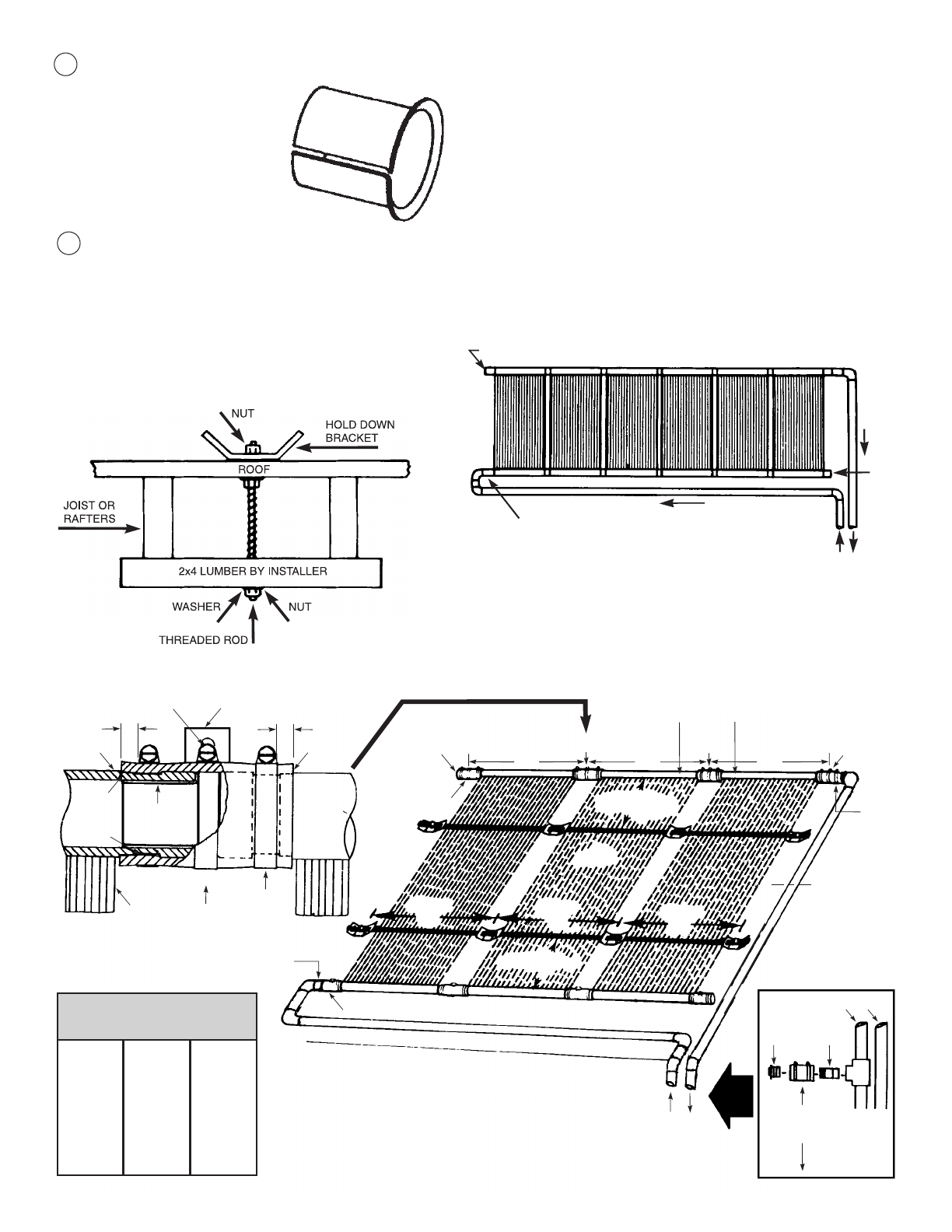
8
Figure 1
ASSEMBLY ON
ROOF DIAGRAM
DISTANCE BETWEEN PANEL
HEADERS AND STRAPS
The Optional Supplemental Hurricane Collector
Hold-Down Kit (Part #12035-1 for 1 1/2”, #12035-2 for
2”) when used in addition to the basic collector installa-
tion kit, meets collector mounting standards in Florida
Counties requiring resistance to 120 mile per hour winds.
In regions where high winds are prevalent, special
mounting precautions may be necessary to secure
brackets to the mounting surface. One method, using
threaded rods, is shown here.
9
HIGH WIND AREA
BRACKET BOLTING
MOUNTING THE SOLAR COLLECTORS
Refer to Figure 1 throughout this section. When mounting
the collectors, always make provisions for inlet connec-
tions at the bottom header and outlet connections at the
top. The outlet headers must be pitched a vertical dis-
tance of at least 8” (20cm) above the inlet headers to
assure proper drainage and uniform flow. Plan the col-
lector location to allow at least one foot on all sides of the
row of collectors for mounting brackets and piping. The
outlet pipe for each row of collectors must be connected
diagonally opposite the inlet pipe. Refer to Figure 2.
Figure 2
Collector
Panel Size
in feet
_________
12
10
8
6
4
Collector
(A) Distance
inches (cm)
_________
60 (152)
48 (122)
36 (91)
24 (60)
_____
Collector
(B) Distance
inches (cm)
_________
16 (40)


