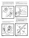
11. Turn the broadcast spreader over so that it rests
on its wheels.
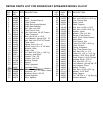
12. Assemble the hitch bracket to the hitch tube. See
figure 8. Secure with two 3/8" x 1-1/4" hex bolts,
3/8" lock washers and 3/8" lock nuts. See figure
8.
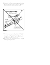
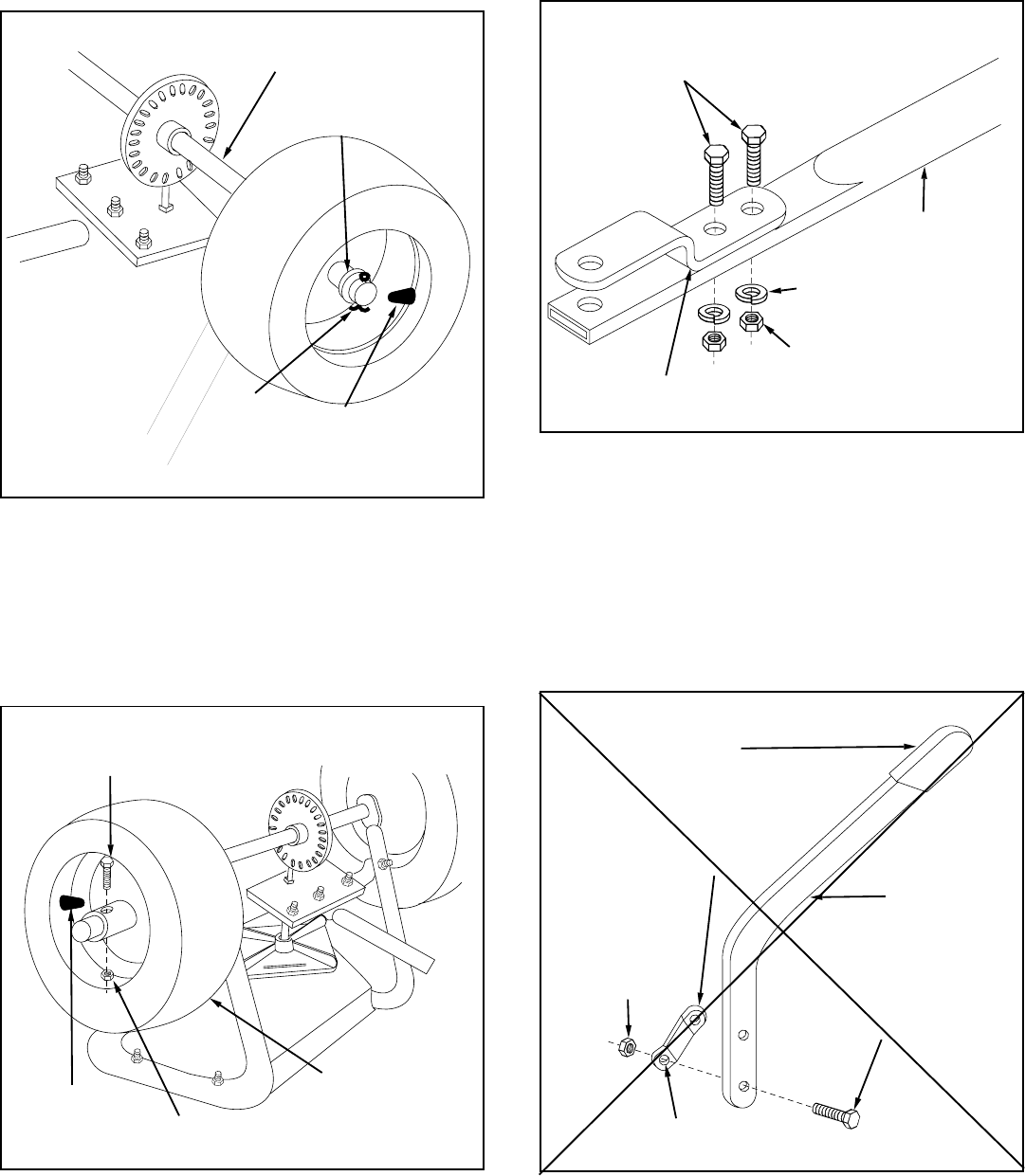
13. Assemble the flow control link (the end with the
smallest hole) to the flow control arm using one
1/4" x 5/8" hex bolt and one 1/4" hex lock nut. See
figure 9. DO NOT OVER TIGHTEN, FLOW CON-
TROL LINK MUST PIVOT FREELY.
14. Place the vinyl grip on the flow control arm. See
figure 9.
FIGURE 8
FIGURE 9
VINYL GRIP
FLOW
CONTROL
ARM
1/4" x 5/8"
HEX BOLT
SMALLEST HOLE
FLOW
CONTROL
LINK
1/4" HEX
LOCK
NUT
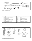
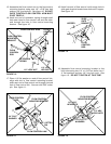
FIGURE 7
3/8" x 1-1/4" HEX BOLT
HITCH TUBE
3/8" LOCK WASHERS
3/8" HEX LOCK NUTS
HITCH BRACKET
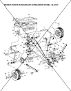
FIGURE 6
AXLE
1-5/8" DIA.
FLAT WASHER
AIR
VALVE
COTTER
PIN
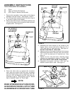
10. Place the drive wheel onto the axle (air valve to
the outside) and secure with 1/4" 1-3/4" hex bolt
and 1/4" hex lock nut. See figure 7.
9. Place wheel assembly without hole through hub
(air valve to the outside) onto axle end having the
smallest and secure with 1-5/8" dia. flat washer
and 1/8" x 1-1/2" cotter pin. See figure 6. Use
extra 1-5/8" diameter flat washer if needed to take
up play.
1/4" x 1-3/4" HEX BOLT
AIR VALVE
1/4" HEX LOCK NUT
DRIVE WHEEL