


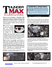
www.Thunder-Max.com 309-360 Installation / Setup Guide V2009.04.23 ProductSupport@ZippersPerformance.com
3
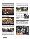
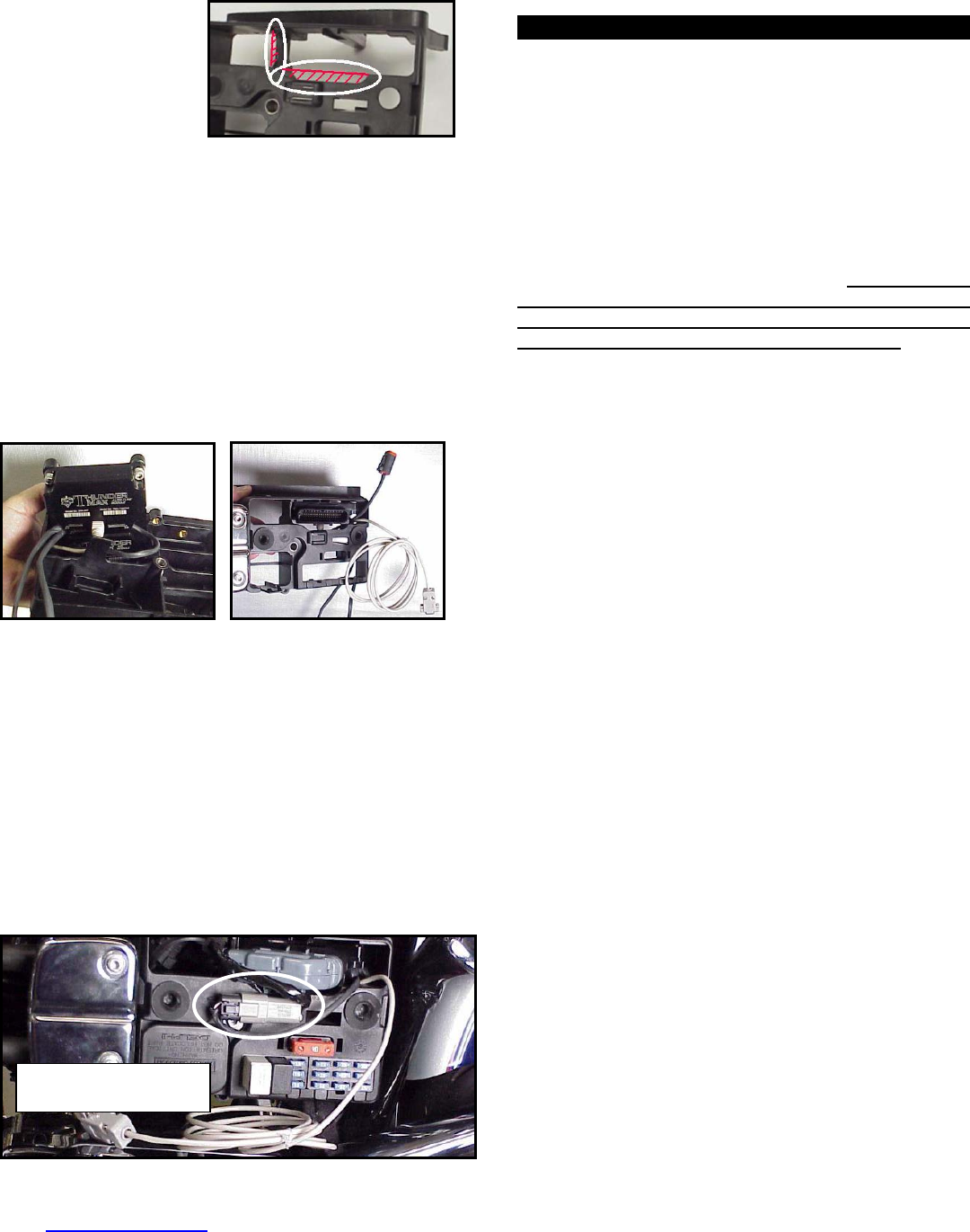
FXD-B: Remove the
stock ECM from the
electrical caddy. The
caddy must be slightly
modified for additional
main harness
connector clearance.
Use a Dremel or Roto-Zip tool to provide additional
clearance for the harness plug catch; also remove
approximately 3/8” from the partition support as shown.
FXD-C: Because of the impossibility of connecting the
communication cable without disassembly once
assembled on FXD models, the cable should be
permanently installed to the ThunderMax, or the optional
entioned in step 2 used. If using the
‘pigtail’ harness m
communication cable, and
feed it and the AutoTune
ECM plug port of the cadd
caddy as shown. The ox
exit towards the opposite side of the cad
if equipped with AutoTune,
power harness through the
y and mount the ECM to the
ygen sensor harnesses should
dy.
FXD-D: If equipped with AutoTune, before reinstalling
the caddy, feed the front cylinder oxygen sensor harness
through to the right side of the bike, over the top and to
the rear of the starter motor. Reinstall the caddy with
fuse and relay blocks in place. Reconnect the TSSM,
coil and ECM harnesses and main fuse. If equipped
ith AutoTune, plug the closed loop module into the
4-pin gray data link on the bike. It is through the data
port that data from the AutoTune module is transferred
to the ThunderMax. A ‘Y’ harness is available (# 309-
343) to keep an open data port if desired. After
programming and setup, the communication cable can
be coiled up and kept under the caddy cover if not using
the ‘pigtail’ harness.
w
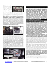
Oxygen Sensor Installation (AutoTune)
If equipped with AutoTune, install supplied wide band
oxygen sensors in the front and rear exhaust pipes.
FXD and all 2007-up models are equipped with
narrow band sensors, which must be removed and
replaced with the supplie d units. The wide
band sensors are long factory sensors.
Installation of the wide ors into factory
headpipes presents no lems, however,
some aftermarket pipes may require exhaust pipe
mo bung relocation for interference-
free sors must mount freely without
contacting surrounding components. If this is not
2006
d wide ban
er than the
band sens
clearance prob
dification or sensor
installation. The sen
possible, do not attempt to bend or modify the
sensor in any way as it is a sensitive electronic
component and will be damaged if you do. Modify
the pipe if required for clearance. Weld-in bungs are
available for exhausts systems not equipped with bungs
or if current bungs present clearance issues. Bungs
should be located no more than 3-4” from the head/pipe
connection (for ideal location, refer to the factory location
on 2007-up models). Weld-in bungs are available from
Zipper’s (#272-200, straight; #272-202, angled). After
installation, route the sensor harness away from the
engine and along the frame when possible, above the
lowest frame point to avoid the possibility of dragging
ground during operation. Avoid routing harnesses where
engine movement or moving parts can contact and
damage the harnesses or connector plugs.
Connect the sensors to the closed loop module. The
AutoTune harness for the rear cylinder sensor is shorter
and can be easily identified by black tracers on all of its
wires; both plugs are clearly marked for front and rear
use. It is very important to install these correctly or the
engine will perform poorly! Tie the harnesses to the
frame or existing component harnesses, taking care to
avoid contact with any vibrating component that may
chaff the sheathing or wires. Some disassembly of bike
components may be required for best harness routing.
FXD Tips: The rear harness mounts easily, just coil
the excess wires and locate them above the
transmission. The front harness should travel from the
AutoTune module, over and to the rear of the starter
motor, behind the exhaust support bracket and between
the crossover pipe and the transmission.
Remove the footpeg/brake pedal bracket mounting bolts
and move the assembly towards the exhaust pipe.
Route the front exhaust sensor harness under the cam
cover exhaust support bracket and behind the brake
pedal; connect it to AutoTune harness.
The sensor plug and harness will drop down to the frame
rail with a little brake pedal wiggling where it can be zip-
tied to the frame rail, out of sight and out of harm’s way.
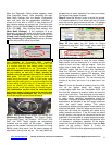
Dyna
®
: ECM installed with
communication cable attached.