5
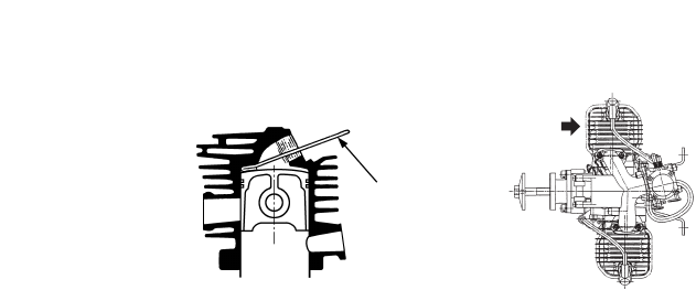
2. Put the stopper (P/N.2670-96220) into a sparkplug hole (Fig.1) of the cylinder(✽) which
is located closer to the rotor than other cylinder when viewed from intake manifold side
(Fig.2).
3. Turn the rotor counterclockwise until piston touches the stopper.
4. Unscrew the rotor nut.
5. Remove the rotor by using the puller (P/N. 1490-96101).
Do not hit the crankshaft end by metal hammer, that may cause the crankshaft to be
bent out of alignment.
c. Assembling crankcase
1. Apply grease on the oil seal lips and oil on the bearing.
2. Assemble the crankshaft with a new gasket.
3. When both front and rear crankcases are tightened, the portion of gasket protruding on
the cylinder mount surface should be cut off with a knife until the gasket becomes flush
with the cylinder mounted surface.
d. Assembling piston
Before assembling the piston, apply the oil on the small end bearing and piston, and set
the piston ensuring that the arrow mark on the top of piston is directed toward the
direction of exhaust port.
e. Re-assembling cylinder and intake manifold
1. Coat the oil on the inner surface of cylinder.
2. The piston is provided with a knock pin which stops the piston ring from turning. Set the
split section of piston ring at the knock pin and assemble the cylinder ensuring not to
break the piston ring.
3. Keep cylinder bolts unfastened before installing the intake manifold to the cylinder.
4. Fixing the intake manifold to the intake port of each cylinder.
5. Then, tighten cylinder bolts.
f. Assembling rotor
Make sure to put lock tight (Medium strength type: TreeBond 1322N, LOCTITE 242,243,
PACER ZAP Z-42) on the rotor fixing nut (P/N:1100-43231).
g. Recommended tightening torque for bolts/nuts
Be sure to follow the recommended tightening torque for bolts/nuts in assembling at each
part.
1. Rotor nut (M10) : 250 ~ 300 kg-cm
2. Crankcase bolt (M5) : 50 ~ 90 kg-cm
3. Cylinder bolt (M5) : 50 ~ 90 kg-cm
4. Engine mount bolt (M6) : 80 ~ 120 kg-cm
5. Propeller hub bolt (M6) : 80 ~ 120 kg-cm
6. Source coil bolt (M4) : 15 ~ 20 kg-cm
h. Adjusting air gap of coil.
The air gap of coil should be adjusted to 0.3 mm (0.01").
i. Adjusting ignition time.
This engine with the point-less C.D.I. type requires no adjustments of ignition time.
Fig. 1
Fig. 2
(✽)
Stopper


