


8 English
in the U.S. There may be other codes and regulations
applicable to your installation:
To make DC wiring connections:
1. Before making any connections, route the positive
and negative battery cables directly to the DC
connection terminals on the Sine Wave Inverter. Slide
the plastic terminal connector covers (boots) over
the positive and negative cables (the red boot slides
on the positive cable and the black boot slides on the
negative cable). Do not route the cables through an
electrical distribution panel, battery isolator, or other
device that will add additional voltage drops except
for the required fuse or breaker on the positive
battery terminal. Install the inverter so that the
battery wire length is as short as possible. The
connectors on the Sine Wave Inverter are designed
to fit up to 250 MCM crimp-on ring terminals (either
AMP or ILSCO) or box connectors (these tighten
on connected cable using a set screw). Note, the
coloured terminal covers (boots) fit much better with
crimp-on ring terminals, and these are recommended
over the box connectors.
2. Neatly cut the cables to the correct length and strip
enough insulation to properly install the ring
terminals or connectors. Attach the terminals to both
cables using the crimp tool recommended by the
manufacturer of the ring terminals. There must be
no stray wire strands protruding from the terminal.
Connect the terminal on the positive cable to the
positive battery connector (stud) on the inverter
and tighten with a wrench to a torque of 9–10 ft-lbs
(11.7–13 Nm). Test that the cable is secure and is
connected to the correct positive terminal.
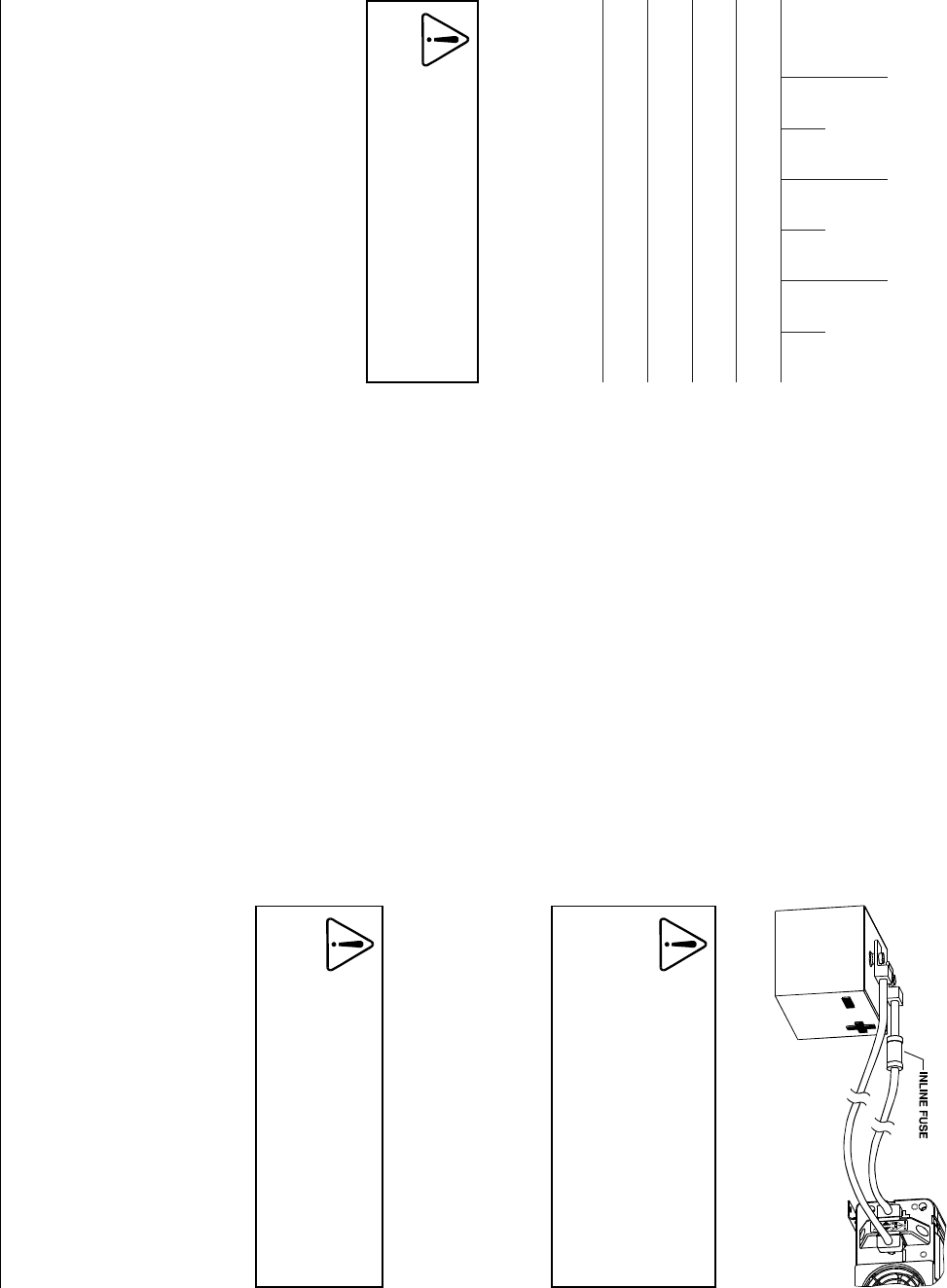
3. An inline fuse between the Sine Wave Inverter and
the battery is required by regulations for all
installations. Again, refer to Table 4 for examples of
correct fuse sizing for some regulations. This fuse
protects your battery and wiring in case of an
accidental short circuit during installation of the
inverter or later damage to the wiring. The fuse and
fuse holder need to be installed in the positive side
of the DC circuit, as close as possible to the batteries
and within the distance specified by the applicable
installation code. Ensure all other power and ground
connections have been made to the Sine Wave
Inverter before connecting the DC cables to the
batteries.
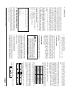
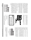
4. Connect the cable from the POSITIVE connector on
the Sine Wave Inverter to the POSITIVE (POS +)
terminal on the fuseholder. Observe the polarities
carefully while performing the installation and do
not reverse the polarities. Route both cables before
making any connections.
5. Connect the DC NEGATIVE cable to the
NEGATIVE (NEG -) terminal on the battery. Next,
connect the cable to the negative terminal on the
inverter. The connection to the negative terminal of
the Sine Wave Inverter should be the last connection
made. A spark when making this final connection
is normal.
6. For residential installations, a DC wiring enclosure
is required to cover the DC connections. Contact
Xantrex or your distributor for this part. For non-
residential installations, slide the rubber terminal
boot covers up the cable and over the terminal
connections.
CAUTION
Clean battery terminals before making
connections. Wear eye protection to keep
corrosion from coming in contact with eyes.
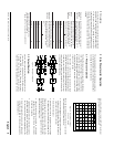
Figure 4. Battery Connections
CAUTION
An inadvertent reverse polarity connection
may cause damage to the Sine Wave
Inverter and it will require servicing (internal
fuse will open). Before making the final DC
connection, observe polarities to ensure
that the wiring is correct.
WARNING
Make sure all the DC connections are tight
(torque to 9–10 ft-lbs, 11.7–13Nm). Loose
connections will overheat and could result
in a potential fire hazard.
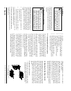
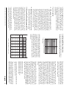
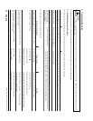
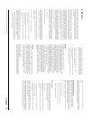
Table 4. DC wire sizes and inline fuse requirements
ledoM
eniraM
noitallatsnI
)1(
VR
noitallatsnI
)2(
laitnediseR
noitallatsnI
)3(
eriW
GWA
esuF
)A(
eriW
GWA
esuF
)A(
eriW
GWA
esuF
)A(
V210001
21i0001V
4#5714#0511#051
V420001
42i0001V
8#098#096#07
V210081
21i0081V
1#0031#5220/4052
V420081
42i0081V
6#0014#0512#521
1
Based on ABYC Recommended Practice E-9, 75°C wire
2
Based on NFPA 70, Article 551, 90°C wire
3
Based on NFPA 70, Article 240 and 310, 75°C wire
Xantrex Sine Wave Inverter Owner’s Manual