


English 11
approximately three seconds, and then turn the
switch back to (I) position. “POWERSAVE ON”
will now be displayed during the start-up sequence
and when the normal state display appears, a small
pointer will be visible, indicating POWERSAVE mode
is enabled. Repeat the same procedure for disabling
POWERSAVE mode.
3.5 Inverter Operating Limits and
Protection Features
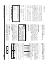
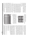
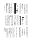
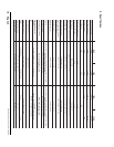
Power Output: The Sine Wave 1000 Inverter will
continuously deliver 1000 watts and the Sine Wave 1800
delivers 1800 watts continuously. The following table
displays the continuous and peak current ratings as well
as surge rating, depending on the model:
Each unit above will be able to operate all AC loads
rated at or below these power ratings. Some high-
horsepower induction motors used in pumps and other
motor-operated equipment require very high surge
currents to start and the Sine Wave Inverter/battery
combination may have difficulty starting these loads. If
you have problems with certain loads, ensure that battery
connections are solid, your DC cables are appropriately
sized, and that the battery is of sufficient capacity and
fully charged.
Input Voltage: The Sine Wave Inverter operates from
an input voltage ranging from:
10 to 16 VDC for 12 V models
20 to 32 VDC for 24 V models
Peak performance for these inverters occurs when DC
input voltage is in the range of 12 volts to 15 volts for
12 V models and 24 volts to 30 volts for 24 V models.
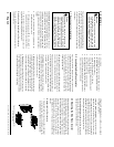
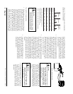
The Sine Wave Inverter will indicate high and low DC
voltage conditions as follows:
The over-voltage protection and shutdown protects the
inverter against excessive input voltage, should the unit
be connected to a higher voltage than it is designed for
(up to 35VDC—higher voltages may cause damage).
Low input voltage shutdown protects your battery from
being over-discharged. The inverter requires a manual
reset to re-start after shutdown from either high or low
input voltage. Turn the power switch to (
##
##
#) and then
back to (I) to re-start the unit.
Output Overload Protection: A short circuit may be
applied to the output continuously without damage to
any internal components. The Sine Wave Inverter will
shut down in less than five seconds when the output
falls 10% below the nominal voltage as a result of current
limiting.
AC Backfeed Protection: Although the Sine Wave
Inverter has been designed to withstand incoming AC at
the AC output, this is only a safeguard and continuous
AC backfeed could lead to inverter damage. Avoid inverter
damage by double checking the AC input and output
wiring on hardwire configured models before applying
power and by understanding your source of AC and
where power from the source leads to (e.g. do not plug a
live extension cord into the AC outlet of the inverter).
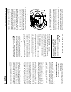
Input Reverse Polarity Protection: The internal
circuitry of the Sine Wave Inverter is protected by an
internal, 32 V, fast-blow fuse as follows:
This fuse is only replaceable by qualified service
personnel. In many reverse polarity conditions, this fuse
will protect internal circuits, however, certain high
voltage/current situations may cause internal damage.
4. Testing
The following simple test procedure should ensure that
the inverter is connected and installed properly.
To test the Sine Wave Inverter:
1. Double check all wiring terminals on the inverter to
observe correct polarity and secure connections.
2. Turn rocker switch to (I) position.
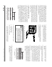
3. Observe the power-up sequence on the display. The
normal-state inverter display of input current and
input voltage should come up.
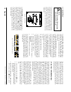
4. Plug a test load (e.g. a light bulb) into the outlet of
the Sine Wave Inverter. The load should function
normally. Observe the output power bar graph—it
should increase with load demand.
5. For hardwire and transfer relay-equipped versions,
plug a load into the AC output leg of the inverter
while input AC is available. Remove input AC. The
load should still operate normally. Replace the source
AC input power and again, the load should operate
normally, indicating proper installation and function
of the transfer relay.
6. Repeat test 4 or 5 with the inverter in
“POWERSAVE” mode.
7. The Sine Wave Inverter is now ready for operation.
ledoM
CAsuounitnoC
tnerruCtuptuO
gnitaR
CAkaeP
tnerruCtuptuO
gnitaR
gnitaRegruS
sttaw.xam(
5rofdereviled
)sdnoces
0001
A3.8A520051
0081
A51A540092
i0001
A3.4A110051
i0081
A8.7A020092
ledoM
tupnICD
revo
egatlov
mrala
tupnICD
revo
egatlov
nwodtuhs
tupnICD
rednu
egatlov
mrala
tupnICD
rednu
egatlov
nwodtuhs
V21
sledom
CDV8.51CDV0.61CDV5.01CDV0.01
V42
sledom
CDV6.13CDV0.23CDV0.12CDV0.02
ledoMledoM&gfM
V42-0001
V42-i0001
ro08NNCdluoG/esuflettiL
A08detar08NNAnnamssuB
V21-0081
V21-i0081
A522ageMesuflettiL
srehtollAA521ageMesuflettiL
Xantrex Sine Wave Inverter Owner’s Manual