


INSTALLATION CONT.WHISTLER FEATURES
FEATURE DESCRIPTIONS
3
1
9
8
7
2
6
4
5
3
10
12
1
9
8
7
2
6
10
12
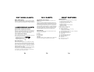
• POP
™
Mode Detection
• Seven Segment Icon Display
• High Gain Optical Lens
• Stay Alert
™
• Total Band Protection
™
• 360° Total Perimeter Protection
™
• VG-2 Cloaking
™
Technology
• 3 City Modes
• Quiet/Auto Quiet Modes
• Vehicle Battery Saver
• Setting Saver
• Alert Priority
• Safety Warning System
™
1758
1773
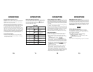
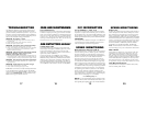
Feature Listings of 1758 and 1773
1758 & 1773 Accessories: Windshield Bracket Kit & Power Cord
11a
Whistler’s ergonomic and user-friendly design provides a
new level of operating convenience. Special features
include:
Note: Not all units have all features listed.
1. Bracket Release Button –
Provides quick and
easy release of the mounting bracket.
2. Speaker – Provides distinct audio warnings for X,
K, Ka band radar, safety radar, laser and VG-2.
3. Mounting Bracket Location – Slot holds mounting
bracket firmly.
4. Radar Antenna – Compact, high-efficiency antenna
receives radar signals.
5. Front Laser Antenna – High gain optical lens provides
increased sensitivity and field of view for leading-edge
laser detection.
6. Rear Laser Antenna – An integrated optical
wave-guide provides superior detection of laser
signals transmitted from behind.
7. City Button - Reduces the annoyance of false
alerts typically encountered in urban driving areas.
8. Quiet/Menu Button - Pressing QUIET before a
signal is detected engages Auto Quiet Mode which
automatically reduces the audio level after the initial
warning to a low audio level setting. Pressing QUIET
during a radar/laser encounter silences audio alerts,
while allowing visual alerts to keep you informed.
(Pressing and holding for 2 seconds allows you to
enter Option Select Mode—see page 12—1773 only.)
9. Power/Dim Dark - Turns unit on/off and engages
Dim/Dark modes (press and hold for 2 seconds).
10. Volume Up/Down Buttons – Adjust volume up or down.
11a. Text Display (1773 only) – Provides distinct visual
confirmation of signals detected, signal strength,
and indicates engaged modes of operation.
11b. 7 Segment Icon Display – Provides numeric signal
strength indicator and band identification.
12. Power Jack – Provides connection for the power cord.
4
5
6
• POP™ Mode - Detection Capability—see page 14
•
Total Band Protection™ - Complete Band Coverage
that detects laser, radar, VG-2 and safety radar bands.
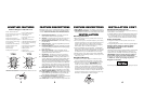
Mounting Guidelines
• Mount the unit as low as possible near the center
of the windshield.
• Do not mount your unit behind wipers, ornaments,
mirrored sunscreens, etc. These obstructions have
metal surfaces which can affect radar and laser
signals and reduce critical warning time. (Regular
tinted glass does not affect reception.)
• Some windshields have an Instaclear
™
or Electriclear
™
type coating, which affect radar signals. Consult your
dealer or the owner’s manual supplied with your vehicle
to determine if your windshield has this coating.
• Avoid placing unit in direct contact with windshield.
• To reduce the possibility of theft, conceal your unit
when not in use.
Windshield Mounting
• Install the two suction cups and rubber bumper
onto the bracket by fitting them into their holes.
• Press the suction cups onto the windshield at the
location you have chosen.
IMPORTANT: Some
newer cars have a plastic safety coating on the
inside of the windshield. The windshield bracket
may leave permanent marks on this type of surface.
To find out if your vehicle has this type of windshield,
check the owner’s manual or ask your dealer. We
recommend that you do not leave the suction cup
bracket on the window in direct sunlight.
FEATURE DESCRIPTIONS
Windshield Mounting (Cont.)
If the detector is removed, this may cause blistering
of the dash in some vehicles.
• Slide the detector onto the bracket until it locks into place.
• If necessary, the unit may be leveled by bending
the windshield bracket. Press the bracket release
button and remove the detector before bending.
Power Connection
• Plug the small end of the power cord into the
unit’s power jack.
• Plug the large end into the vehicle’s cigarette lighter.
NOTE: Cord fits tightly into detector. When
installing the cord, expect some resistance.
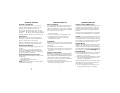
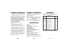
Fuse Replacement
The lighter socket plug is equipped with a replaceable
2 amp 3AG fuse located behind the silver tip. To
replace the fuse, carefully unscrew the tip of the plug.
IMPORTANT: Unscrew slowly. The tip contains a
spring which may fly out when disassembling.
Insert the new fuse with the spring and screw on the
tip.
With use, screw cap on plug may loosen.
Retighten occasionally.
Unscrew the tip of the lighter socket plug carefully when replacing the 2 amp fuse.
• POP
™
Mode Detection
• Real Voice
®
Alerts
• Text Display
• High Gain Optical Lens
• Stay Alert
™
• Total Band Protection
™
• 360° Total Perimeter Protection
™
• VG-2 Cloaking
™
Technology
• 3 City Modes
• Quiet/Auto Quiet Modes
• Vehicle Battery Saver
• Setting Saver
• Alert Priority
• Safety Warning System
™
11b
INSTALLATION