


8
CONNECTING IF BATTERY IS OUTSIDE OF VEHICLE
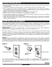
a) Check polarity of battery posts- For top-mounted battery connectors, the positive post (marked POS, P, +)
usually has a larger diameter than the Negative battery post (marked NEG, N, –). For side-mounted battery
connections the Positive terminal is red, the Negative terminal is black.
b) Attach a 24-inch (minimum length) 6 AWG insulated battery cable to the Negative battery post (marked
NEG, N, –).
c) Connect the Positive (RED) battery clamp to the Positive battery connector (marked POS, P, + or red).
d) Stand as far back from battery as possible, and do not face battery when making final connection.
e) Carefully connect the Negative (BLACK) charger clamp to the free end of the battery cable connected to the
negative terminal. Connect the charger's power cord to a grounded 110/120 volt AC power outlet, and refer
to Appendix A for approximate charging times.
f) Set charger's charge rate to appropriate setting according to battery size.
g) When charging is complete, disconnect cables and clamps in reverse order from which they were connected.
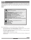
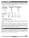
CHARGING TIMES
The VEC093 is a fully automatic battery charger. It automatically adjusts the charge rate as the battery becomes
charged and stops charging when the battery is fully charged. If you require some estimate of the time it takes
to charge a battery refer to Appendix A for these details.
100A ENGINE START
The Engine Start Function can supply at least 100 Amps of current for engine starting. Follow all batter, frame
and AC connection precautions as if charging a battery in a vehicle. Observe the Reverse Polarity LED and dig-
ital display to make sure that faults are not indicated. Pressing the 100A pushbutton will immediately place the
charger in the 40 ampere charge mode. The digital display will indicate a countdown to “000.” This initial
charge on the battery makes sure that the battery is able to take a charge. When the “000” count is reached,
the Start Your Engine LED lights. This indicates that the high current circuit is enabled and will energize when
the engine starts cranking. Crank the engine using manufacturer’s guidelines, typically in 3 to 5 second bursts.
The high current engine starting function requires a rest/cooling period between tries. Wait 4 to 5 minutes
before a second attempt at starting the engine. During the rest period, the battery is charging at 40 amps.
Crank the engine until it starts.
After the engine starts, press the ON/OFF button, disconnect the charger from AC, then frame and
battery connections.
RECONDITION MODE
NOTE:
BATTERY RECONDITION mode does not charge any battery. Charging is a separate operation. The battery to
be treated does not have to be installed in a vehicle. Follow the instructions for Connecting If Battery is Outside of Vehicle.
RECONDITION MODE should only be used with 10 Amp Hour or larger capacity lead-acid batteries. Charge the
battery to be treated for 20 minutes, before using RECONDITION Mode. Observe the Digital Display for any codes.
This initial charge will check the battery for shorted cells (F01), open cells or battery too low (or overcharged) to
accept a charge (F02), and to ensure the battery can take a charge. If code F03 is displayed, change modes to the
RECONDITION MODE.
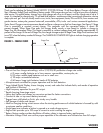
Whenever a lead acid battery begins to discharge, lead sulfate, an insulator, begins to build up on the plates in the
battery. This reduces the ability of the battery to hold a full charge. When that battery has an immediate charge, most of
the lead sulfate is dissolved and the plates are freed of this insulation. If a battery remains in a discharged condition, the
lead sulfate changes to a hard crystalline form, making a full charge difficult. BATTERY RECONDITION mode sends a
sequence of electronic pulses into the battery, shaking loose and dissolving the crystals.
VEC093
A062003