


8
4.2 PRINCIPLES OF OPERATION
The power inverter converts power in two stages. The first stage is a DC-to-DC conversion
process that raises the low voltage DC at the inverter input to 145 volts DC. The second stage
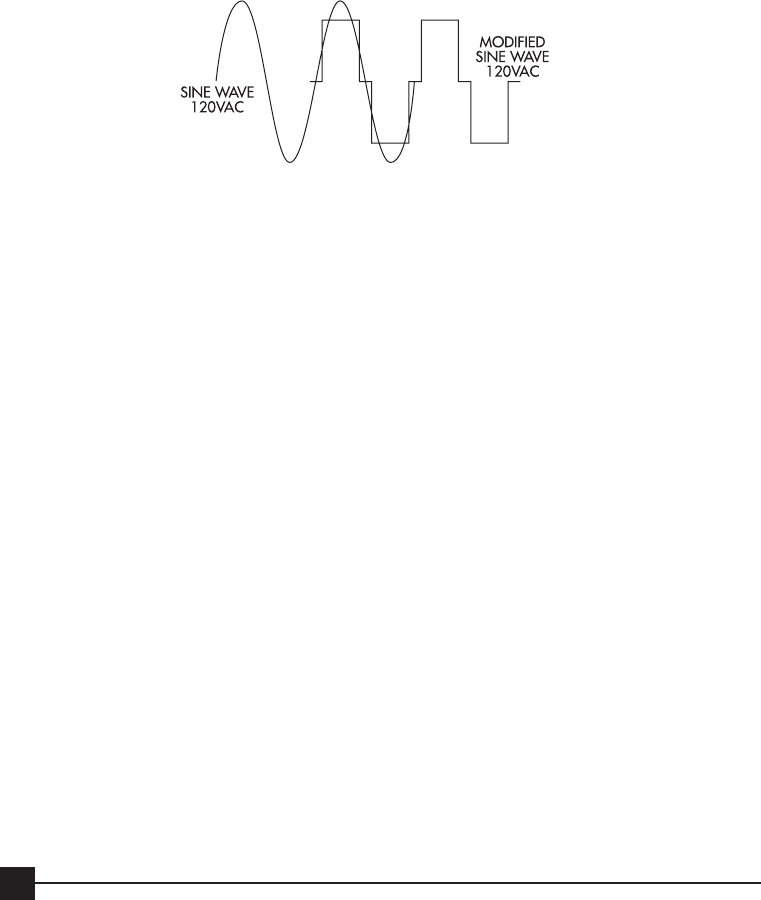
is the actual inverter stage that converts the high voltage DC into 120 volts, 60 Hz AC, Modi-
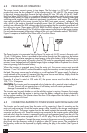
fied Sine Wave (MSW). MSW is a waveform that has characteristics similar to the sine wave
shape of utility power. This type of waveform is suitable for most AC loads, including linear and
switching power supplies used in electronic equipment, transformers, and motors. The modified
sine wave produced by the power inverter has an RMS (root mean square) voltage of 120
volts, which is the same as standard household power. Most AC voltmeters (both digital and
analog) are calibrated for RMS voltage under the assumption that the waveform measured will
be a pure sine wave. These meters will NOT READ the RMS voltage of a modified sine wave
correctly. They will read about 20 to 30 volts low when measuring the output of the power inverter.
For accurate measurement of the output voltage of this unit, use a voltmeter marked “TRUE RMS”.
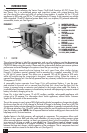
Figure 5 compares a Modified Sine Wave with a True Sine Wave.
FIGURE 5
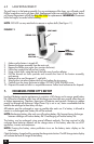
The Power Inverter is incorporated into the Power City main unit. It’s DC source is the main unit’s
12 volt, 19AH battery. Power is provided to the inverter through two flat contacts on the bottom
of the inverter. The inverter operates on stored energy in the main battery. With a full charge on
the main battery, the inverter will supply a load of 100 watts for approximately one hour and 5
minutes. Lower wattage loads will operate longer, higher wattage loads will operate for a shorter
time using energy from the main battery.
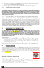
When the inverter is operated away from the main unit, the power source must provide
between 11 and 14.5 volts DC and must be able to supply the necessary current (amps) to operate
the load. The power source may be a battery or a well-regulated DC power supply. To obtain a
rough estimate of the current (in amperes) that the power source must deliver, simply divide the
power consumption of the load (in watts AC) by 10.
Example: If a load is rated at 100 watts AC, the power source must be able to deliver:
100 / 10 = 10 amperes
CAUTION: The inverter must be connected only to batteries with a nominal output voltage of
12 volts. The unit will not operate from a 6 volt battery and will sustain permanent
damage if connected to a 24 volt battery.
The inverter may be used whether or not the vehicle’s engine is running. However, the inverter
may not operate while the engine is starting since the battery voltage can drop substantially
during engine cranking. The inverter draws less than 0.06 ampere from the battery when it is
not supplying power to a load.
4.3
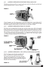
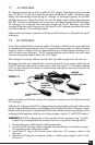
CONNECTING INVERTER TO POWER SOURCE AWAY FROM MAIN UNIT
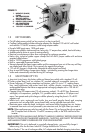
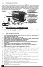
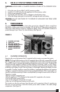
The Inverter can be used away from the main unit by removing it from it’s mounting on the
main unit and powering it from the Inverter power cable, located in the storage compartment
in the back of unit. The power inverter has two flat metal contacts that normally mate with the
connector on the main unit. These flat contacts are connected to the inverter power cable (black
and red color) when the inverter is removed from the unit and operated away from the unit. The
inverter power cable comes equipped with a 12 volt DC plug. The tip of the plug is positive and
the side contact is negative. Connect the power inverter to the power source by inserting the DC
plug firmly into the accessory outlet of a vehicle or other DC power source. The connection to
the accessory outlet can be improved by slightly rotating the plug in the socket. (See Figures 6
and 7)