


INSTALLATION DIRECTIVE
27
V08 ENT M75
-
M11
-
M12
MAY 2006
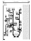
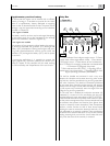
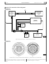
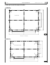
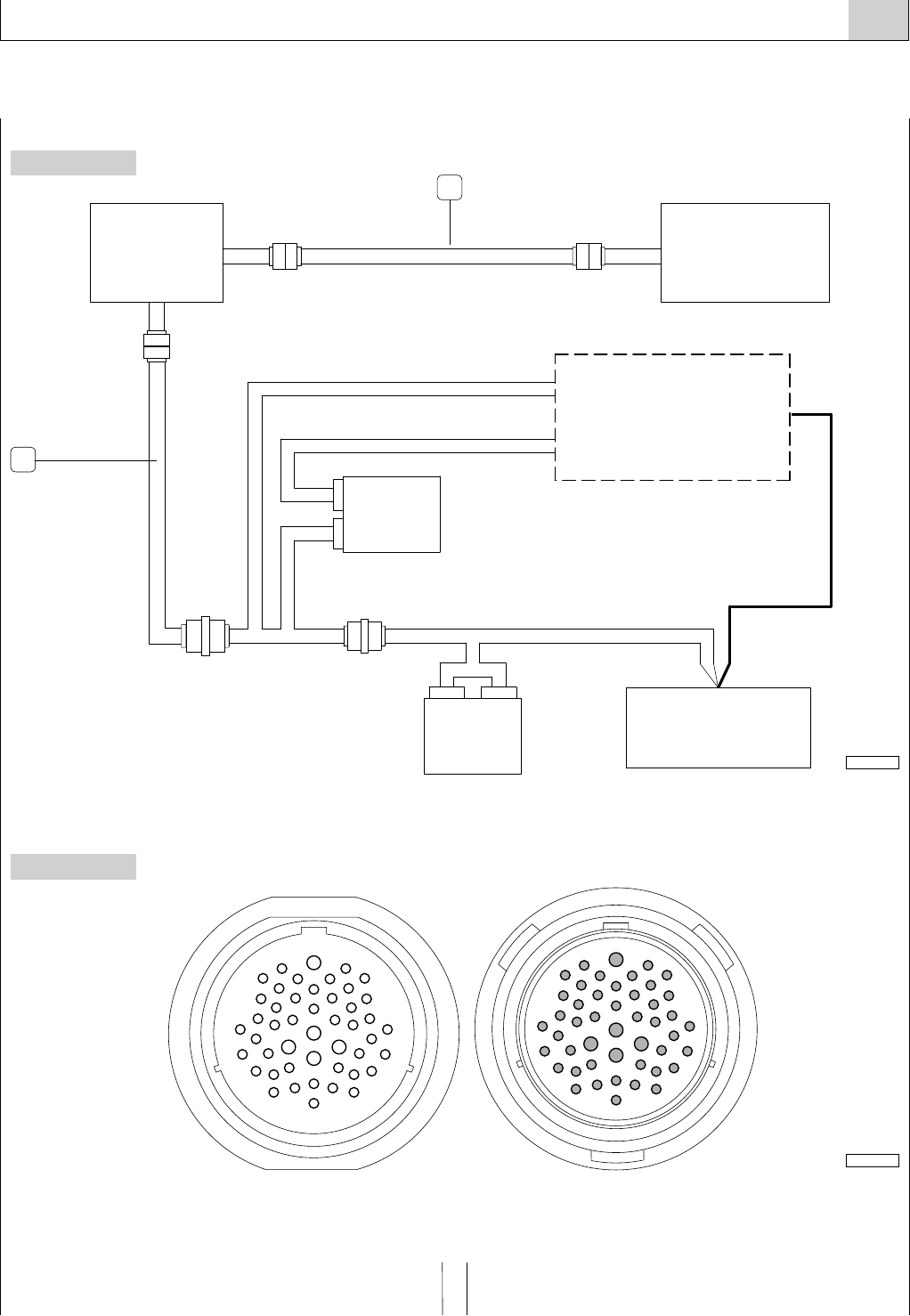
Synoptic of the connections of the analog panels
Figure 24
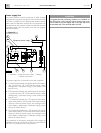
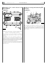
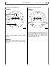
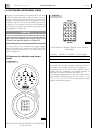
CONNECTORS OF THE EXTENSION WIRE HARNESS JB - JC, SEEN FROM THE COUPLING SIDE
Figure 25
The JC-JB wire harness comprises 47 lines, each connected
to the terminal identified on both connectors by the same
number.
To identify the functions served by the individual lines, refer
to the electrical diagrams in Chapter 20.
1. JB-JC Extension wire harness - 2. JE-JH Extension wire harness.
1
2
JC JB
32
47
18
28
45
17
29
44
16
42
43
31
46
30
7
11
12
24
38
1
5
6
13
14
15
4
40
2627
41
25
39
21
22
36
34
8
9
19
20
33
35
23
37
2
3
10
24
12
40
39
22
38
37
23
36
44
16
13
14
41
26
25
27
15
28
42
43
1
11
4
10
2
3
7
5
17
6
18
35
21
9
20
19
33
8
32
34
47
29
45
30
31
46
04_250_N
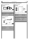
ENGINE
EQUIPMENT
MAIN
INSTRUMENT
PANEL
SECONDARY
INSTRUMENT
PANEL
RELAY
BOX
JB
JA
JF2
J1
EDC
JF1
J2
JH JH
JEJE
JC
JC
06_131_V
BATTERY