


Contractor Rac Pro
INSTRUCTION MANUAL
5
4 Contractor Rac Pro
INSTRUCTION MANUAL
TracRac Inc. 994 Jefferson Street, Fall River, MA 02721-4893 • 800-501-1587 TracRac Inc. 994 Jefferson Street, Fall River, MA 02721-4893 • 800-501-1587
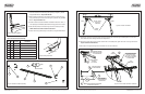
8A. Attach each crossbar onto a left and right upright by inserting the T-bolts through the saddle plate and corner brace
holes. Attach 6 locknuts leaving them loose for adjustments.
8B. Center the crossbar left to right. Crossbar should fit flat on the saddle plats, tighten the T-bolt nuts using 15mm socket.
Torque T-bolt nuts to 220-240 in-lbs.
9. Follow steps 1 through 6 (See Figure 9) to install the front and rear cantilevers.
Figure 8. Crossbar installation.
Figure 9. Front and Rear Cantilever installation.
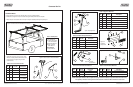
5. Insert the rubber block into the stake pocket opening and tighten up the bolt
using 5/16 Allen Wrench. Torque to 90-110 in-lbs.
6. Slide one clamp into the base of each upright. Position as shown and secure
using socket head cap bolt and U-channel. Tighten up the bolt using 5/16 Allen
Wrench. Torque to 130-150 in- lbs.
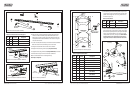
7A. Build two standard crossbar assemblies. Assemble two tie downs–items 1, 2
and 3 (See Figure 7 and Table 5). Slide them into the top groove of the crossbar.
7B. Slide 6 T-bolts (item 5) into the bottom groove of the crossbar (3 per side).
NOTE: The flat recess of the crossbar must face down.
7C. Attach the end caps (item 6) using screws (item 7) using 5mm Allen Wrench.
Figure 5. Upright installation.
Figure 6. Clamp attachment.
Item
No.
1
2
3
4
5
6
7
Qty.
2
2
2
1
6
2
2
Table 5. Standard Crossbar Assembly
Description
Tiedown
Knob, Female 3/8-16 UNC
T-Bolt 3/8-16X1-1/8, SS
Crossbar, Triple T-Slot
T-Bolt, M10X1.5, 25mm
Crossbar Endcap
Bolt M6X1
Part No.
10-25111
KB-90004
HD-80122
01-10540
HD-80218
PI-23325
HD-23276
Figure 7. Standard crossbar assembly.
CLAMP
BASE
TOP
FRONT
BOTTOM RECESS
4
5
6
7
4
1
2
3
EQUAL DISTANCE
SADDLE
SADDLE
CORNER
BRACES
LOCK NUT, M10X1.5
P/N HD-23179
15MM SOCKET
EQUAL DISTANCE
SLIDE REAR CANTILEVER
(SHORT FOR SHORT BED)
ON T-SHAPE NUT BAR
SLIGHTLY UNSCREW
TWO BOLTS
(13mm SOCKET)
SLIDE CLAMP ASSEMBLY
ON REAR CANTILEVER
SLIGHTLY UNSCREW TWO
BOLTS AND SLIDE
FRONT CANTILEVER ON
T-SHAPE NUT BAR
ALIGN REAR CANTILEVER WITH REAR UPRIGHT
AND TIGHTEN UP TWO BOLTS
FRONT
CANTILEVER
SLIDE FRONT CANTILEVER INTO
CLAMP CENTER CLAMP AND
TIGHTEN UP FOUR BOLTS
(15mm AND 17mm SOCKETS)
THEN TIGHTEN UP TWO BOLTS
OF FRONT UPRIGHT
REAR
CANTILEVER
1
2
6
4
5
3