


LF502
2
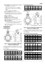
Principal materials:
Case
— carbon steel
Linings
— The following are the standards:
Teflon PFA for Meter sizes 150 mm (6”) to 400
mm (16”), chloroprene rubber for Meter sizes
500 mm (20”) and 600 mm(24”)
Electrodes
— 316L stainless steel (standard)
Grounding rings
— 316 stainless steel (standard)
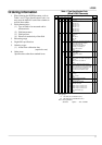
See Table 1 for optional materials and other
related information.
„
Converter Specifications
Input signals
Analog input:
voltage signal from detector and is
proportional to process flow rate
Digital input (DI)
Voltage signal: High level 20 to 30 V
dc
Low level 2 V
dc or less
Input resistance: 2.7 k:
Number of inputs: one point
DI function
— One of the following functions can
be assigned to DI signal:
• Unidirectional 2-range switching signal
(lower range with high DI voltage level)
• Bidirectional 2-range switching signal
(lower range with high DI voltage level)
• Totalizer start/stop
— Starts and stops the
built-in totalizer. (Totalizer starts with high DI
voltage level and stops with low DI voltage
level.)
• Zero adjustment
— Starts zero adjustment (on-
stream at zero flow rate) when DI voltage level
goes
low
after
remaining
high
for
10
to
20
seconds.
• Fixed-value outputs
— Outputs fixed values
for current output (and pulse output if used).
Outputs fixed values when DI voltage is high.
Output signals
Analog output:
4–20 mA
dc;
Load resistance 0 to 1 k:
Digital outputs:
— 2 points (D1 and D2)
Output type: Solidstate relay contact outputs
(non polarity)
Capacity: 150 V
dc, 150 mA maximum or
150 V
ac, 100 mA maximum (peak)
Number of outputs: Two points
D1 and D2 functions
— Two of the following
functions can be assigned to D1 and D2.
•
Pulse output (available only for D1)
Pulse rate: 3.6 to 360000 pulses/hour
Pulse width: 5 to 100 ms (but less than half of
the period for 100 % flow rate)
• Multi-range selection outputs
(1) One point (D1 or D2) output
Unidirectional 2-range automatic selection
signal or bidirectional 2-range automatic
selection signal
(2) Two point (D1 and D2) outputs
Unidirectional 4-range automatic selection
signal or bidirectional 4-range automatic
selection signal
•
High and/or low limit alarm outputs
Outputs an alarm signal if the flow rate output
goes above high limit value or below low limit
value
Setting range: –10 to 110 % of range
Output
status: Contact
ON
when
alarm
occurs.
•
Empty pipe alarm output
Outputs an alarm signal if the detector pipe is
emptied.
Output
status:
Contact
ON
when
alarm
occurs
•
Preset point output
Outputs a signal when the built-in totalizer
count reaches the preset point.
Setting range: 1 to 999999 counts
Output
status:
Contact
ON
when
alarm
occurs
•
Converter failure alarm output
Outputs an alarm signal if the converter detects
an erroneous condition other than high/low
limit or empty pipe alarm conditions.
Communications output
— A digital signal is
superimposed on 4–20 mA
dc current signal
(conforms to the HART protocol).
Load resistance: 240 : to
1
k:
Load capacitance: 0.22 µF maximum
Note:
HART (Highway Addressable Remote
Transducer) protocol is a communications
protocol for industrial sensors recommended by
HCF (HART Communication Foundation).
Output display:
2-line,16-character LCD display
(backlit) shows flow rate and total flow in various
engineering units. Up to two set of data can be
displayed.
Damping:
5 to 600 s
Parameter settings:
Configuration parameters can
be set using the control keys on the LCD display.
Zero and span calibration:
Built-in calibration signal source allows converter
unit check.
Zero adjustment:
Zero point adjustment can be
started by pressing a combination of control keys
on the LCD display.
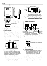
Conditions when power fails:
The output and display will remain as follows
when power fails. Parameter setting values are
stored in non-volatile memory and the values will
be re-stored
when
the
power
returns
to
normal
condition.
• Current output: 0 mA
dc
• LCD display: No display
•
Digital output: OFF