


PCB Layout Guideline
www.ti.com
2.7 Procedure
2.7.1 Power Supply
Make sure EQUIPMENT SETUP steps are followed.
Disconnect LOAD #1. Turn on PS#1.
Measure → V(J1(VBUS)) = 6.5V ± 200mV
Measure → V(J2(VBAT)) = 0V ± 200mV
Measure → V(J4(VTSB)) = 0V ± 200mV
Observe → D1 (PG) ON, D2 (CHG) OFF
2.7.2 Charger Enable and Battery Detection
Connect JP1; Connect 2-3 of JP7 (Charger ON)
Measure → V(J4(VTSB)) = 2.2V ± 300mV
Connect 2-3 of JP5 (Internal TS);
Adjust R6 until V(JP4-1) = 0.7V ± 200mV
Measure → V(J2(VBAT))=4.2V 200mV
Observe → D1 (PG) ON, D2 (CHG) OFF
2.7.3 Charge Current/Voltage Regulation
Reconnect LOAD#1. Turn on. Use the constant voltage mode.
Connect JP1; Set the output voltage to be 2.2V.
Measure → I(J2(VBAT)) = 0.1A ± 50mA
Observe → D1 (PG) ON, D2 (CHG) ON
Increase the voltage of LOAD#1 to be 3.5 V.
Measure → I(J2(VBAT)) = 0.5A ± 100mA
Observe → D1 (PG) ON, D2 (CHG) ON
2.7.4 VDPM ((Input Voltage Regulation) Setting)
Disconnect J3, measure the resistance between J3-1 to GND (6.65kΩ ±10%)
2.7.5 Test Complete
Turn off the power supply and remove all connections from the unit under test (UUT).
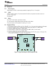
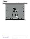
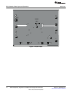
3 PCB Layout Guideline
1. It is critical that the exposed thermal pad on the backside of the bq24210 package be soldered to the
PCB ground. Make sure there are sufficient thermal vias right underneath the IC, connecting to the
ground plane on the other layers.
2. Decoupling capacitors for VBUS, BATC should make the interconnections to the IC as short as
possible.
3. Take the EVM layout for design reference.
6
800mA, Single-Input, Single Cell Li-Ion Battery Solar Charger with Power Path SLUU477–December 2010
Submit Documentation Feedback
© 2010, Texas Instruments Incorporated