Manual: 151-082010 300-302 Series Page 5 of 31
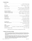
1.2. Specifications
Accuracy .................................................................................... < ±0.75% full scale (F.S.) at 3σ
(±1.0% F.S. for >10 slm versions)
Repeatability .............................................................................±0.05% of reading + 0.02% F.S.
Maximum Pressure........................................................................................500 psi [3.45 MPa]
(With high pressure option) 1000 psi [6.9 MPa]
Pressure Coefficient .................................................. <0.01% of reading/psi [0.0015%/kPa] (N2)
See pressure section for higher pressure errors.
Operating Temperature ....................................................0-60°C in non-condensing environment
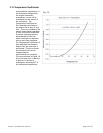
Temperature Coefficient (zero) .................................... Maximum ±0.1%F.S./°C (from 0 to 60°C)
Temperature Coefficient (span) ..................................Maximum ±300 ppm/°C (from 15 to 50 °C)
Maximum ±450 ppm/°C (from 0 to 60 °C)
Leak Integrity ...............................................................................................<1x10⁻⁹ std. cc/s.
Flow Ranges .................................................................. 0-5 sccm to 0-25* slpm. (N2 Equivalent)
Standard Output ........................................................................... 0-5 VDC. (load min 2k Ohms)
Optional Output ............................................................................ 4 -20 mA. (load < 600 Ohms)
Power Requirements ..................................................................... ±(15) VDC @ 55 mA (meters)
± (15) VDC @ 150 mA (controller)
Class 2 power 150VA max
Wetted Materials ................................................................................ stainless steel, nickel 200
Attitude Sensitivity of zero ..............................................< ±0.7% F.S. for 90° without re-zeroing
{N2 at 19.7 psia (135 KPa)}
Weight ............................................................................................................ 1.93 lb [0.88 kg]
Electrical Connector............................................................................... 15 pin subminiature “D”
Fitting Options................... ¼” Swagelok®, 1/8” Swagelok®, VCR®, VCO®, 9/16”-18 Female thread
Face Seal to Face Seal Length ................................................................ 1.88”(47.75 mm) VCR®
(Specifications may vary for instruments with ranges greater than 10 slpm)
1.3. Optional 4-20 mA Current Output
An option to the standard 0-5 VDC output is the 4-20 mA current output that is proportional to flow.
The 4 - 20 mA signal is produced from the 0 - 5 VDC output of the flow meter. The current loop output
is useful for remote applications where pickup noise could substantially affect the stability of the
voltage output.
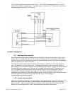
The current loop signal replaces the voltage output on pin 6 of the “D” connector. The current loop
may be returned to either the signal common or the -15 VDC connection on the power supply. If the
current loop is returned to the signal common, the load must be between 0 and 600 ohm. If it is
returned to the -15VDC, the load must be between 600 and 1200 ohm. Failure to meet these
conditions will cause failure of the loop transmitter.


