


MAINTENANCE (Continued)
ÅÅ ALTERNATOR AND BATTERY (if so equipped):
A. ALTERNATOR:
For electrical problems such as inoperative starter or discharged
battery see equipment manufacturer’s instructions for fuse replacement,
maintenance and repairs.
B. BATTERY:
1. When servicing battery, always connect cables to battery exactly as
they were before removal (ground cable to battery negative [- or
neg.] post). If incorrectly connected, fuse (if so equipped), will blow
and alternator won’t charge battery. If this happens, connect cables
correctly and replace fuse.
2. Never expose engine ignition system to battery power. If battery
cable or any live wire contacts ignition system ground wire, engine
ignition system may be damaged.
3. If external battery charger is used, disconnect positive (+ or pos.)
cable from battery to prevent possible damage.
4. See battery manufacturer’s instructions for service and storage.
ÆÆ CHECK ENGINE AND EQUIPMENT OFTEN FOR LOOSE NUTS,
BOLTS AND ATTACHMENTS AND KEEP THESE ITEMS
TIGHTENED.
ADJUSTMENTS
DO NOT MAKE UNNECESSARY ADJUSTMENTS. FACTORY SETTINGS
ARE SATISFACTORY FOR MOST CONDITIONS. IF ADJUSTMENTS ARE
NEEDED, PROCEED AS FOLLOWS:
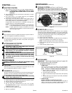
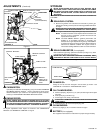
ÀÀ REMOTE CONTROL (see Figure 8 or 9):
For satisfactory engine performance, engine and equipment control must
be adjusted properly. To check engine control adjustments, proceed as
follows:
Set equipment control at “FAST” or “HIGH SPEED” and keep it in this
position. In this position, engine control lever should touch “HIGH SPEED
STOP”. If it does, the controls are adjusted correctly and no further
adjustment should be necessary.
NOTE: If engine control lever does not touch “HIGH SPEED STOP”,
proceed to CONTROL A in Figure 8 or CONTROL B in Figure 9.
CONTROL A (see Figure 8):
A. Loosen clamp screw so remote control cable can be moved in cable
clamp (do not remove cable clamp from control bracket or disconnect
remote control cable from engine control lever).
B. Move engine control lever so it is touching “HIGH SPEED STOP” and
hold it in this position.
C. Tighten clamp screw securely so cable clamp will hold remote control
cable in place when equipment control is used.
The engine controls should now be adjusted correctly.
If additional adjustments are needed, make them at the equipment control
(see equipment manufacturer’s instructions).
CONTROL B (see Figure 9):
A. Hold control lever in an upward position, as close as possible to “HIGH
SPEED STOP’’ and loosen, but do not remove remote cable stop
screw.
B. Move remote cable stop upward on remote control cable so it holds
control lever against “HIGH SPEED STOP” and tighten remote cable
stop screw securely.
The engine controls should now be adjusted correctly.
If additional adjustments are needed, make them at the equipment control
(see equipment manufacturer’s instructions).
Page 4
MAINTENANCE (Continued)
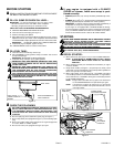
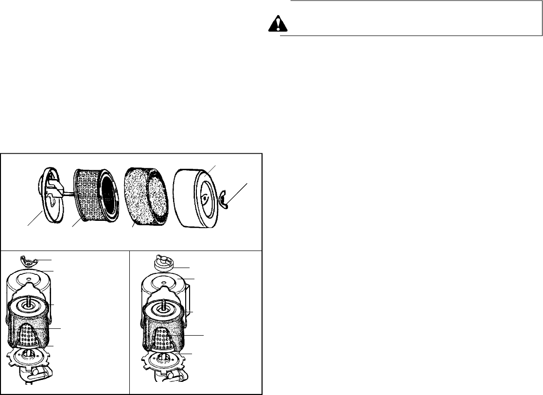
B. TO REMOVE AND INSTALL FILTER(S):
AIR CLEANER "A" (see Figure 7):
1. Remove wing nut and cover.
2. Slide foam filter (if so equipped) off paper filter.
3. Discard paper filter.
4. Clean inside of base and cover thoroughly.
5. Install new paper filter on base.
6. Slide foam filter (if so equipped) over paper filter.
7. Install cover and wing nut. Tighten wing nut securely.
AIR CLEANER "B" & "C" (see Figure 7):
1. Remove wing nut and cover.
2. Slide foam filter off paper filter.
3. Inspect filters for discoloration or dirt accumulation. If either is
present, service per preceding “TO SERVICE FILTER(S)”
instructions.
4. Remove paper filter (if service is necessary).
5. Clean topside of base and inside of cover thoroughly.
6. Install paper filter .
7. Slide foam filter over paper filter.
8. Install cover and wing nut. Tighten wing nut securely.
NOTE: In Air Cleaner “C” application, make sure to position scoop
correctly:
• WINTER (Below 32
0
F; 0
0
C): Scoop should be pointed directly
at muffler.
• SUMMER (Above 32
0
F; 0
0
C): Scoop should be pointed towards
blower housing (approximately 45
0
clockwise from “winter posi-
tion”).
IMPORTANT: In order for engine to operate smoothly and effi-
ciently, it is important for scoop to be in proper position for sea-
son.
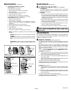
Figure 7
181-630-14
BASE
FOAM FILTER (IF SO EQUIPPED)
PAPER FILTER
COVER
WING NUT
WING NUT
COVER
FOAM FILTER
PAPER FILTER
BASE
AIR CLEANER "B"
AIR CLEANER "A"
AIR CLEANER "C"
WING NUT
COVER
FOAM FILTER
PAPER
FILTER
BASE