ENGLISH
GB
Do not short circuit the battery’s termi-
nals. Sparks occur which can result in
fire. Do not wear metal jewellery which
can come into contact with the battery
terminals.
In the event of damage to the battery
casing, cover, terminals or interference
to the strip covering the valves, the bat-
tery should be replaced.
If the battery terminals are coated with oxide, they
should be cleaned. Clean the battery terminals with
awirebrushandgreasethem.
Position the battery in the appropriate place under
the engine casing and thread over the battery
mount in accordance with fig. 2. Press down the
mount into the appropriate holes. Place the locking
nuts in the wing nuts. Thread the washers onto the
battery mount’s legs from below and secure with
the wing nuts so that the battery is securely mount-
ed. Connect the battery cables.
NOTE! To avoid damage to the engine and the bat-
tery, the positive battery cable (+) should always
be connected to the battery first.
Do not run the engine when the battery is dis-
connected.
TYRE PRESSURE
Check the air pressure in the tyres. Correct air
pressure:
Front: 1.7 bar (24 psi)
Rear: 0.6 bar (9 psi)
CUTTING DECK
The deck’s parallel alignment with the surface can
be adjusted with nuts D at the rear deck suspension
mounts (fig. 3).
Multiclip (Garden Multiclip - Garden Combi):
The unit is installed on the machine on delivery.
Collector (Garden Combi):
The unit is installed on the machine on delivery but
must be completed with ejector tubes.
1. Disconnect the battery cables.
2. Remove the cover C (fig. 4).
3. Install the ejector tube G (fig. 4). Use the same
screws and nuts as were used for the cover.
Under no circumstances may the lawn-
mowerbestartedifthecoverhasnot
been replaced with the ejector tube.
4. Install the battery cables.
GRASS COLLECTOR (Accessory)
Assemble the grass collector according to the sep-
arate assembly instructions supplied with the grass
collector.
The ejector tube G may only be used together
with the complete grass collector.
When using the grass collector, all components
which make up the collector must be installed on
the machine (fig. 5).
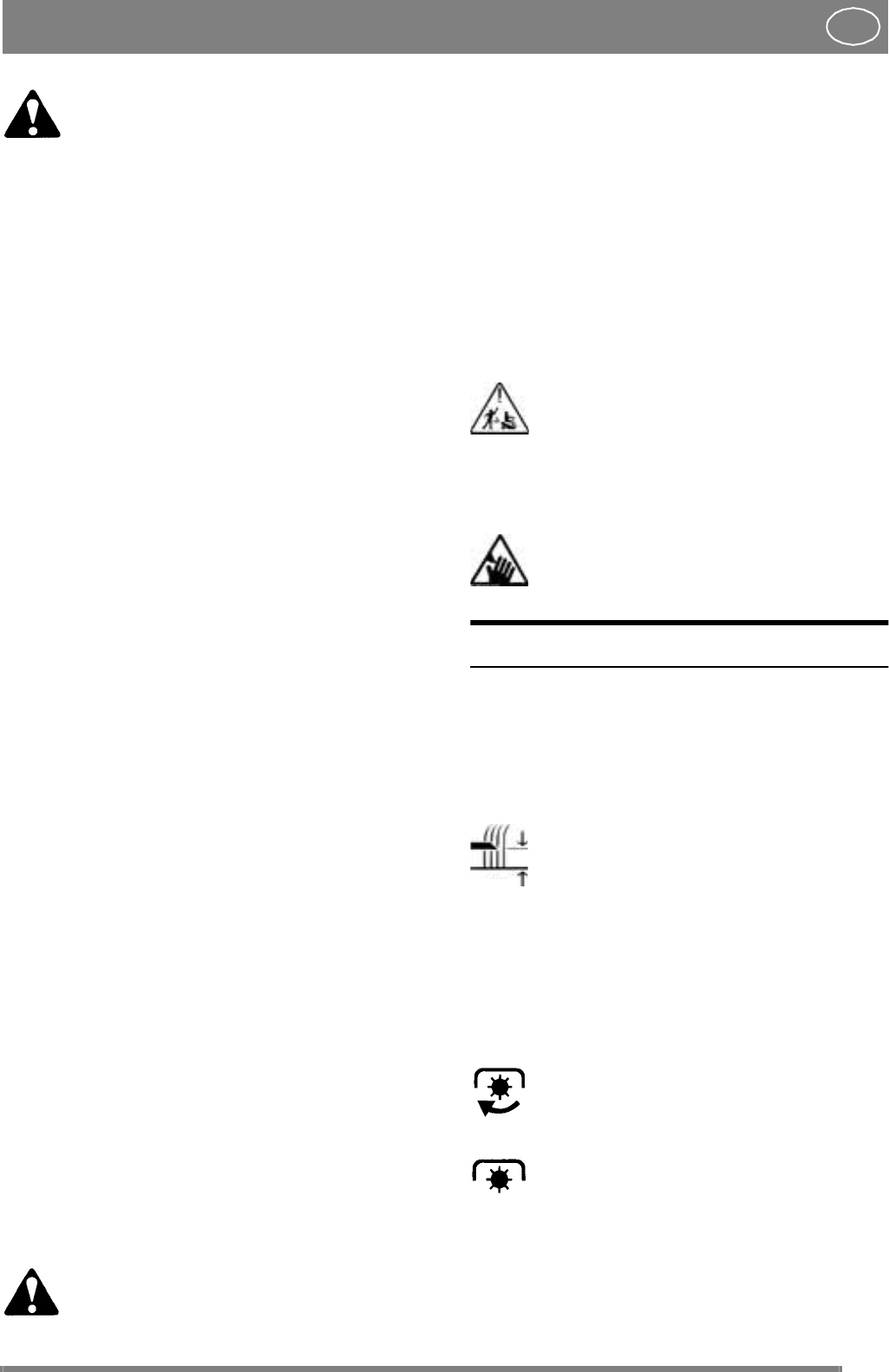
Never use the machine without the col-
lection sack H and the long ejector tube
being installed. There is a risk of stones
and other objects being thrown out, in-
juring people and animals or damaging
property.
Warning for the rotating blade. Never
put your hand or foot in the ejector
opening.
CONTROLS
Items 1 - 7, see figures 18 - 19.
1. HEIGHT SETTING LEVER
Lever for setting the height of the cutting deck
above the ground.
Release the lever by pushing it inwards.
Then move it up or down to the desired
position.
The lever has five positions, giving cutting heights
from 35 to 75 mm.
2. BLADE ENGAGING LEVER
Lever for engaging the drive for the cutting deck.
There are two positions:
1. Lever in the forward position – the
blade rotates.
2. Lever in the rear position – the blade
does not rotate. The blade brake is activat-
ed.
3. SERVICE BRAKE/CLUTCH
A pedal that combines both service brake and
clutch. There are 3 positions:


