


10 ► SM20 User Manual
PREOPERATION PROCEDURES
CHECK POWER SOURCE
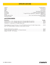
1. Using a calibrated ow meter and pres sure gauge,
make sure the hydraulic power source develops a
ow of 4–6 gpm/15–23 Ipm at 1000-2000 psi/70–140
bar or 7–9 gpm/26–34 lpm at 1000-2000 psi/70/140
bar.
2. Make certain that the power source is equipped with
a relief valve set to open at 2100 psi/145 bar maxi-
mum.
3. Make certain that the power source re turn pressure
does not exceed 250 psi/17 bar.
4. Make sure the pump inlet screen is clear of debris
and the outlet hose is clean. Remove any obstruc-
tion before operating. Refer to PUMP CLEANING
PROCEDURES.
CONNECT HOSES
1. Wipe all hose couplers with a clean lint free cloth
before making connections.
2. Connect the hoses from the hydraulic power source
to the couplers on the sump pump or sump pump
hoses. It is a good practice to connect return hose
rst and disconnect it last to minimize or avoid
trapped pressure within the trash pump motor.
NOTE:
If uncoupled hoses are left in the sun, pressure in-
crease inside the hoses might make them difcult to
connect. Whenever possible, connect the free ends
of the hoses together.
3. Observe the arrow on the couplers to ensure that the
ow is in the proper direc tion. The female coupler on
the sump pump is the inlet (pressure) coupler.
PUMP OPERATION
1. Observe all safety precautions.
NOTE:
The SM20 is not designed for use with a suction
pipe inlet. The diameter of the suction screen at the
bottom of the pump provides maximum pump ef-
ciency. Reducing the size of this inlet will greatly
reduce pump performance.
2. Connect a hose tted with a 2-1/2 inch/63.5 mm
male pipe end to the pump outlet tting. Make sure
the tting is securely tightened. For best perfor-
mance, keep the hose as short as possible and lay
it out to avoid sharp bends or kinks.
3. Lower the pump into the liquid to be pumped. Locate
the outlet end of the discharge hose to disperse the
liquid as required. Remove any kinks from the hose
to assure maximum water ow.
4.
NOTICE
Never point the hose at bystanders.
Turn on the hydraulic power source. Watch for sol-
ids in the liquid being pumped. If solids are exces-
sive, the discharge ow might decrease. If this hap-
pens, stop the pump and check for the cause of the
problem.
Under some conditions, the liquid being pumped
might be slowed enough so It can no longer push
particles in the liquid. If this happens, particles can
accumulate in the hose and backup the pumping
chamber, causing further restriction. The impel-
ler then acts as a “grinding wheel which causes
acceler ated pump wear. Reduced liquid ow can be
caused by the following:
• The pump sinks into solids at the bottom of the
hole.
• The end of the outlet hose is too high, causing
an excessive lift height for the column of liquid
being pushed by the sump pump. This slows the
ow of liquid to a level where it can no longer
carry solids out the end of the hose.
• The ow and pressure of hydraulic uid to the
pump is too low, which re duces impeller speed.
A 20% de crease in hydraulic uid ow can re-
duce pump performance by 50%. When operat-
ing at reduced hydraulic ow and pressure, the
end of the outlet hose should not be more than
40 ft/12 m above the liquid.
5. When pumping is complete, set the hy draulic control
valve to the “OFF” posi tion. Lift the pump from the
work area.
WHEN PUMPING WATER MIXED
WITH SOLIDS
• Do not use a nozzle.
• Remove all hose kinks before starting the pump.
OPERATION