


7
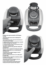
To let you know that the laser is in standby mode, the battery LED fl ashes every 4 seconds.
To deactivate standby mode and restore full operation of the laser, press and hold the laser’s or remote control’s
manual button for 3 seconds.
The laser and all other functions turn on again.
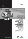
Using the Manual Mode
In horizontal mode pressing the manual button on the laser or the remote control changes the laser from
automatic self-leveling mode to Manual mode. Manual mode is indicated by the fl ashing (once every second)
red LED 5.
In Manual mode (horizontal), the Y-axis can be sloped by pressing the Up- and Down-Arrow-buttons on the
laser‘s keypad or the remote control. Additionally, the X-axis can be sloped by pressing the Left- and Right-Arrow-
buttons on the remote control. To resume automatic self-leveling mode, press the manual button again.
In vertical mode, the laser is always in MANUAL mode. Pressing the up and down arrow buttons align the
laser beam to the right/left side, and the left and right arrow buttons at the remote control adjust the slope of
the laser beam.
To resume automatic self-leveling mode, press the manual button again.
Using the Y- Single Slope Mode
The Manual button on the remote control toggles the unit to Manual, the Y-axis Single Slope Mode, then
Automatic Mode. To activate the Y-axis single slope mode, press the manual button at the remote control twice.
This is indicated by the simultaneously fl ashing red 5 and green 4 LEDs (once every second).
In Y-axis single slope mode, the Y-axis can be sloped by pressing the Up- and Down-Arrow-buttons on the
laser or the remote control, while the X-axis remains in automatic self leveling mode (e.g. when setting up
sloped ceilings or drive ways).
To resume automatic self-leveling mode from Y-axis single slope mode, press the manual button again.
APPLICATIONS
General Construction
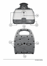
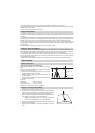
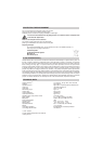
Determining the Height of Instrument (HI)
The height of instrument (HI) is the elevation of the laser’s
beam.
The HI is determined by adding the grade-rod reading to a
benchmark or known elevation.
1. Set up the laser and place the grade rod on a job-site
benchmark (BM) or known elevation.
2. Slide the receiver up/down the grade rod until it shows an
on-grade reading.
3. Add the grade-rod reading to the benchmark to determine
the height of instrument.
Example:
Benchmark = 30.55 m (100.23 ft)
Rod reading = +1.32 m (+4.34 ft)
Height of instrument = 31.87 m (104.57 ft)
Use this HI as a reference for all other elevations.
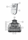
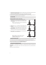
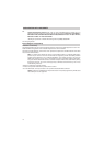
Using the Y-Axis Single Slope Mode
1. Set up the laser over the reference point (A).
2. Look over the rotor to align the laser to the desired direction hub
in the axis that is supposed to be used in automatic self-leveling
mode. Turn the laser on the tripod until it is properly aligned.
3. Attach a receiver to a grade rod. Set the grade rod on the self-leveling
axis direction hub to check the laser’s elevation (B).
Note: Use this HI as a reference for checking the alignment
of the laser after setting the slope for the other axis.
4. Activate the Y-axis single slope mode by pressing the manual button
at the remote control twice.
5. Check the laser’s elevation on the slope axis directly in front of the
laser.
A
C
B
1.32 m (4.34 ft)
30.55 m (100.23 ft)
HI