


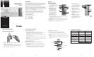

General-Purpose Clamp
The C61 general-purpose clamp allows the receiver to be attached to a
survey rod or wooden pole.
Features and Functions
Attaching the Receiver to the Survey Rod or Wooden Pole
Declaration of Conformity
Application of 89/336/EEC
Council Directive(s):
Manufacturer’s Name: Trimble Navigation Ltd.
Manufacturer’s Address: 5475 Kellenburger Road
Dayton, Ohio 45424-1099 U.S.A.
European Representative Trimble GmbH
Address: Am Prime Parc 11
65479 Raunheim, Germany
Model Number: HR150
Conformance to Directive(s): EC Directive 89/336/EEC using
EN55022 and EN50082-1
Equipment Type/Environment: ITE/residential, commercial
& light industrial
Product Standards: Product meets the limit B
and methods of EN55022
Product meets the levels and
methods of IEC 801-2, 8 kV air,
4 kV contact IEC 801-3, 3 V/m 26
to 1000 MHz 80%, @ 1 kHz
Warranty
Trimble warrants the receiver to be free of defects in material and
workmanship for a period of one year.
Trimble or its authorized service center will repair or replace, at its
option, any defective part for which notice has been given during the
warranty period. If required, travel and per diem expenses to and from
the place where repairs are made will be charged to the customer at
the prevailing rates.
Customers should send the product to Trimble Navigation Ltd. or the
nearest authorized service center for warranty repairs, freight prepaid.
In countries with Trimble subsidiary service centers, the repaired
product will be returned to the customer, freight prepaid.
Any evidence of negligent, abnormal use, accident, or any attempt
to repair the product by other than factory-authorized personnel
using Trimble certified or recommended parts, automatically voids
the warranty.
The foregoing states the entire liability of Trimble regarding
the purchase and use of its equipment. Trimble will not be held
responsible for any consequential loss or damage of any kind.
This warranty is in lieu of all other warranties, except as set forth
above, including any implied warranty merchantability of fitness for
a particular purpose, are hereby disclaimed. This warranty is in lieu
of all other warranties, expressed or implied.
EMC Declaration of Conformity
This receiver has been tested and found to comply with the limits for
a Class B digital device for radio noise for digital apparatus set out
in the Radio Interference Regulations of the Canadian Department
of Communication, and is pursuant to part 15 of the Federal
Communication Commission (FCC) rules. These limits are designed
to provide reasonable protection against harmful interference in a
residential installation. This receiver generates radio frequency. If it’s
not used in accordance with the instructions, it may cause harmful
interference to radio or television reception. Such interference can be
determined by turning the receiver off and on. You are encouraged
to try eliminating the interference by one or more of the following
measures:
• Reorient or relocate the receiving antenna.
• Increase the separation between the laser and the receiver.
For more information, consult your dealer or an experience radio/
television technician.
CAUTION: Changes or modifications to the receiver that are
not expressly approved by Trimble could void authority to use the
equipment.
Receiver Specifications
LED Channels 3
Capture Height 50 mm (2 in.)
Acceptance Angle
90°
On-Grade Sensitivity Medium: 3.00 mm (
1
/8 in.)
Power Source Two 1.5-V batteries (type LR6/AA)
Battery Life @ 20 °C (68 °F) Alkaline: 70+ hours
Low Battery Indicator Red LEDs flash in sequence
Automatic Shutoff 30 minutes after last laser detection
or push-button actuation
Spectral Sensitivity Operates with red visible and
infrared rotating lasers with
wavelength between 610 and
900 nm
Marking Notch 50 mm (2 in.) below top of
receiver, on both sides
Operating Temperature –20 °C to +50 °C
(–4 °F to +122 °F)
Storage Temperature –40 °C to +70 °C
(–40 °F to +158 °F)
Weight 0.3 kg (.75 lb)
Dimensions (H x W x D) 13.6 x 5.0 x 2.8 cm
(5.37 x 2.00 x 1.11 in.)
1. Release Tab—allows the receiver to be locked onto or released
from the general-purpose clamp.
2. Jaws—close/open so that the general-purpose clamp can be
attached to or released from a survey rod or wooden pole.
3. Reading Edge—aligns with the receiver’s on-grade marking
notches.
4. Jaws Screw—controls the closing/opening of the jaws.
5. Circular Bubble Screw Holes—are where the optional
1277-6251S grade rod circular bubble kit is mounted.
1. Slide the general purpose
clamp into the receiver until it
“clicks” into position.
2. Turn the jaws screw
counterclockwise to open the
clamp’s jaws.
3. Slide the survey rod or
wooden pole between the
clamp’s jaws.
4. Turn the jaws screw clockwise
to hold the general-purpose
clamp securely in place.
Trimble Construction Division
5475 Kellenburger Road
Dayton, Ohio 45424-1099
U.S.A.
+1-937-245-5600 Phone
www.trimble.com
© 2006, Trimble Navigation Limited. All rights reserved.
Reorder PN 1277-7571 (11/06)
Notice to Our European Union Customers
For product recycling instructions and more information,
please go to: www
.trimble.com/environment/summary
.html
Recycling in Europe
To recycle Trimble WEEE,
call: +31 497 53 2430, and
ask for the “WEEE associate,” or
mail a request for recycling instructions to:
Trimble Europe BV
c/o Menlo Worldwide Logistics
Meerheide 45
5521 DZ Eersel, NL
– 9 – – 10 – – 11 – – 12 –
– 13 – – 14 –
– 15 –
2 3
4
1
5