


2
Installation Instructions Bumper Kit
Form No. 1732052-01
Rev. 02/2008
Briggs & Stratton Power Products
Copyright © 2008 Briggs & Stratton Power Products Group, LLC
Milwaukee, WI USA. All rights reserved
TP 200-4237-01-AT-UV
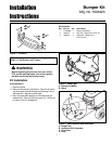
Figure 4.
A. Bumper Assembly
B. Hinges
C. Locknuts, 5/16-18
D. Capscrews, 5/16-18 x 3/4
B
A
BUMPER INSTALLATION
1. Insert 5/16-18 x 3/4 capscrew (D, Figure 4) through
the holes in hinge (B) and the holes in bumper
assembly (A).
2. Connect the 5/16-18 locknut (C) to 5/16-18 x 3/4 cap-
screw (D). Do not tighten at this time.
3. Repeat steps 1 and 2 for all four holes in bumper
assembly (A) and hinges (B).
4. Tighten all hardware.
D
C
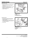
Figure 5. Installation
A. Hinge Post
B. Hood and Grill Assembly
C. Pivot Post
D. Stop
A
C
B
D
HOOD INSTALLATION
1. Set hinge posts (A, Figure 5) onto pivot posts (C).
2. Roll the hood and grill assembly forward until it
reaches the stops (D).
3. Install the socket and bulb (A, Figure 2) by pushing it
into the bezel (B) twisting the socket and bulb clock-
wise. Repeat on other side.
4. Close the hood.