11
Initial Setup & Assembly
INITIAL SETUP & ASSEMBLY
NOTE: Some of the following setup procedures may
already be completed.
Assemble Blade
1. Place the blade on a flat surface.
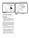
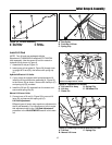
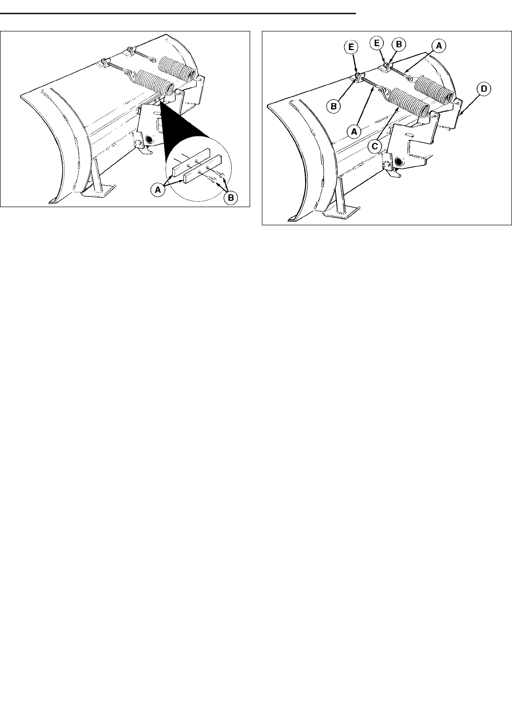
2. Baron/Broadmoor/LT/1600/2600 Series: See Figure
10. Install one bar stop (A) using the two 5/16-18 x 1
taptite screws (B). Do not install second bar stop.
Landlord/GT/1700/2700 Series: Do not install bar
stops.
NOTE: See Figure 10 Generally, these models do not
require the second bar stop to be used. However, if after
adjusting the skid shoes all the way up, the blade is not
able to make contact with the surface being plowed, bar
stops must be added. Remove the dozer blade and
install the second bar stop flush against the first one and
remount blade assembly.
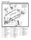
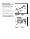
3. See Figure 11. Insert threaded end of eyebolt (A)
through lug on blade, and screw on 5/16 nut (B) just
far enough so that it is flush with the end of the eye-
bolt.
4. See Figure 11. Hook the springs (C) into the pivot
frame (D). Using a pliers, stretch the springs to hook
the opposite ends to the eyebolts (A).
5. See Figure 11. Tighten the nut (B) on each eyebolt
enough to expose about 3/4" (19 mm) of thread.
6. See Figure 11. Holding the first nut (B) with a
wrench,add a second nut (E) to each eyebolt, and
tighten securely against the first nut to act as a jam
nut.
Figure 11. Tension Springs
A. Eyebolt D. Pivot Frame
B. Nut, 5/16 E. Nut, 5/16
C. Spring
Figure 10. Bar Stop
A. Bar Stops
B. Taptite Screws, 5/16-18 x 1


