


49
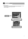
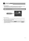
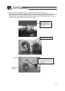
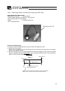
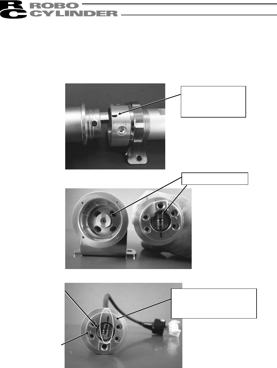
5) Align the tab on the replacement motor unit with the countermark on the cylinder.
With the motor unit and cylinder aligned properly, insert the coupling into the replacement motor unit by
aligning the orientation of this coupling with that of the actuator coupling (adjusted to a position
corresponding to a rod projection of 2 mm from the mechanical end). Apply countermarks to identify
the current motor position (phase Z position) and coupling.
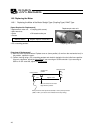
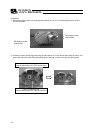
Position the couplings.
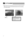
Align the tab on the
replacement motor unit
with the countermark on
the cylinder.
Coupling
Replacement
motor unit
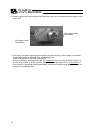
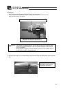
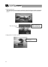
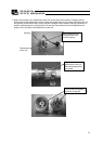
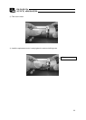
After the coupling has been
inserted, apply countermarks
on the replacement motor unit
and coupling.