


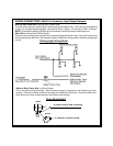
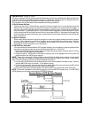
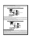
Dark Blue Wire: Delayed 300mA Pulsed Channel 3 Output
The Dark Blue wire supplies a 300mA ground pulsed output whenever channel three of the receiver is
accessed. Pressing the pre-programmed transmitter button for three seconds will access channel three.
This is a low current output and must be connected to a relay to supply power to the trunk release or the
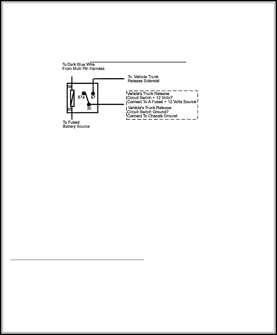
circuit you wish to control. Connect the Dark Blue wire to terminal # 86 of a VF45F11 P&B relay or
equivalent. Connect terminal # 85 of the relay to a fused + 12 volt source. Connect the common, normally
open, and normally closed contacts of the relay to perform the selected function of channel 3. See below
for relay wiring detail.
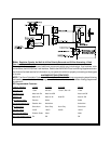
Channel 3 Relay Wiring Detail
12
Green w/ Black Trace Wire: 300mA Latched Channel 4 Output
The Green w/ Black Trace wire supplies a 300 mA switched output whenever channel four of the receiver is
accessed. Pressing the pre-programmed transmitter button(s) will access channel four and will remain
active for as long as the transmitter button(s) is held. This is a low current output and must be connected
to a relay to supply power to the device you intend to control. Connect Green w/ Black Trace wire to
terminal #86 of a VF45F11 P&B relay or equivalent. Connect terminal #85 of the relay to a fused + 12 volt
source. Connect the common, normally open, and normally closed contacts of the relay to perform the
selected function of the channel 4 output.
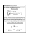
Dark Blue/Black Trace Wire: External Trigger Input
The Dark Blue/Black trace wire allows the remote start unit to be activated from an external source. The
intent of this wire is to allow the unit to be controlled from a "POSSE/CAR-LINK" paging system or similar
device. When this wire receives a ground pulse, the unit will start the vehicle. Connect this wire to a ground
pulsed output from the controlling circuit.
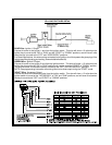
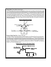
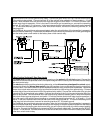
Black w/ White Trace Wire : 300 mA Horn Output
The black w/ white trace wire is provided to beep the vehicle’s horn. This is a transistorized low current
output, and should only be connected to the low current ground output from the vehicle’s horn switch.
If the vehicle uses a + 12 VDC horn switch, then connect the black w/ white trace wire to terminal 86 of the
AS 9256 relay ( or an equivalent 30 Amp automotive relay ), and connect relay terminal 85 to a fused + 12
VDC battery source. Connect relay terminal 87 to the vehicle’s horn switch output, and connect relay
terminal 30 to a fused + 12 VDC battery source.
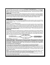
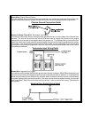
WIRING THE 4 PIN AUXILIARY OUTPUT HARNESS
The auxiliary 4 pin connector provides low current outputs to control various functions in the vehicle during
different stages of the Remote Start unit's operation. Understanding these outputs and the time in which
they occur will allow you to determine if they are needed for the particular vehicle you are working on as well
as how to use them.
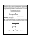
Black w Blue Trace Wire: Pulsed Ground Output Before Start
The Black w/ Blue Trace wire will provide a 1 second 300 mA pulsed ground output 1.5 second before the
remote start unit activates as well as when the transmitter is used to disarm the system. Typical use for
this output would be to disarm a factory theft deterrent system to prevent false triggering of the factory
alarm when the remote start unit engages or when the 9675 is used to unlock the doors.
Black w/ Light Green Trace Wire: Pulsed Ground Output After Start
The Black w/ Light Green Trace wire will provide a 1 second mA pulsed ground output after the vehicle is