


109821_0508 21
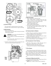
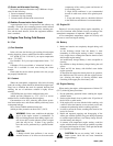
(2) Valve Clearance Adjustment
The valve clearance must be adjusted every 1000 operat-
ing hours, or whenever the valve rocker is abnormally noisy,
or if there is an engine malfunction and the fuel system is
working properly.
Valve clearance : 0.20 mm (0.008 in) (When the engine is
cold.)
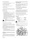
Adjustment Procedure
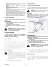
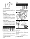
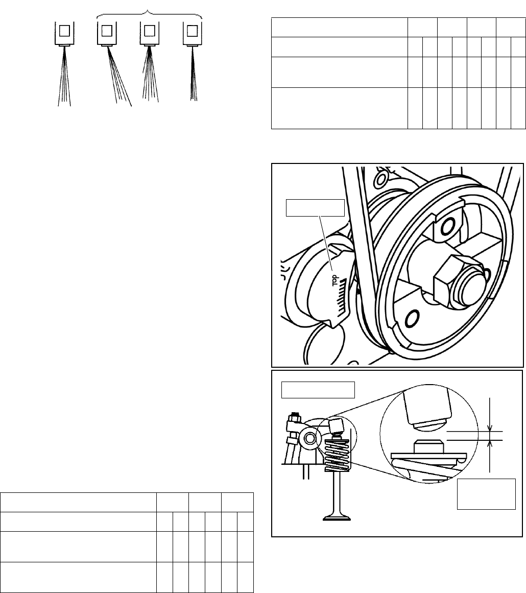
1. Bring No. 1 cylinder to the top dead center in the com-
pression stroke by aligning the top mark of the crank pul-
ley with top mark of the timing gear case.
2. Remove the cylinder cover and turn the crankshaft in the
forward and backward directions.
If the inlet and exhaust valves of No. 1 cylinder do not
move at this time, No. 1 cylinder is at the top dead center.
When the valves move, give another full turn to the
crankshaft and align the top mark of the crank pulley
with the TOP mark of the timing gear case.
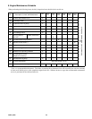
Model:E673L, N843, N843L
3) Using the table below reference position of #1 piston and
adjust as necessary, measure and adjust the clearance of
the valves.
4) On completion of the valve clearance adjustment in step
3 above, realign mark as in step 1 above by rotating the
crankshaft one complete revolution.
Then measure and adjust the clearance of the remaining
unadjusted valves.
I: Inlet E: Exhaust
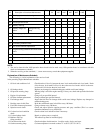
Model:N844L, N844L-T
3) Using the table below reference position of #1 piston and
adjust as necessary, measure and adjust the clearance of
the valves.
4) On completion of the valve clearance adjustment in step 3
above, realign mark as in step 1 above by rotating the
crankshaft one complete revolution.
Then measure and adjust the clearance of the other
valves.
I: Inlet E: Exhaust
(3) Adjustment of Injection Timing
The injection timing should not be readjusted. Refer to
Engine Service Manual.
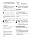
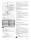
(4) Cylinder Compression Pressure Measurement
The cylinder compression pressure measurement should
be done every 2000 operation hours, or whenever the engine
output is reduced.
Compression pressure: 2.94 Mpa (426 psi)
Test condition: Cranking speed 200 rpm
Coolant temperature 75°C (167°F)
Repair the engine and/or replace parts if compression pres-
sure is lower than 2.45 Mpa (355 psi)
Cylinder No. 1 2 3
Valve arrangement I E I E I E
When No. 1 cylinder is at TDC in
the compression stroke X X X X
With the crankshaft rotated 360° in
normal direction from above X X
Good
Faulty
Cylinder No. 1234
Valve arrangement I E I E I E I E
When No. 1 cylinder is at TDC
in the compression stroke X X X X
With the crankshaft rotated
360° in normal direction from
above
XX XX
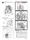
TOP Mark
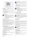
Adjust screw
Valve
clearance